Advisor: José Pertierra-Arrojo
In collaboration with: Harsh Kedia and Kyle Bancroft
Independent Study Statement
This independent study aims to research and explore the possibilities of robotic fabrication and digital-to-material workflows for the purposes of designing with as-found materials. The intention is to understand the larger set of affordances provided by robotic technologies when it comes to the development of new techniques for fabrication and design. To this end, we hope to explore and add to the knowledge base of subtractive fabrication (namely, milling) through robotic arms. The goal is to develop advanced fabrication techniques to open-up and rethink the use and design of as found materials such as raw or kiln-dried wood logs. Our hope is that this exploration both creates interesting precedent for new ideas and projects, but also serves as a design project, where we focus on the design of a particular object, with specific uses and constraints that can then be deployed out into the world.
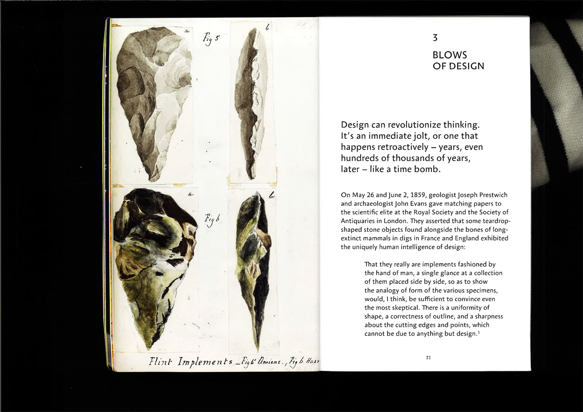
Image Of Early Designed Rock Tools From “Are We Human?” By Beatriz Colomina And Mark Wigley
Goals
“On May 26 and June 2, 1859, geologist Joseph Prestwich and archaeologist John Evans gave matching papers to the scientific elite at the Royal Society and the Society of Antiquaries in London. They asserted that some tear drop shaped stone objects found alongside the bones of long extinct mammals in digs in France and England exhibited the uniquely human intelligence of design. That they really are implements fashioned by the hand of man, a single glance at a collection of them placed side by side, so as to show the analogy of form of the various specimens, would, I think, be sufficient to convince even the most skeptical. There is a uniformity of shape, a correctness of outline, and a sharpness about the cutting edges and points, which cannot be due to anything but design.” - Are We Human?
In other words, these were the blows of design. Design was applied directly to an as found object to shape it into something usable and aesthetic. Over time, design changed. During and since the industrial revolution, design became about taking mass-produced objects and assembling them into industrial products - it seemed as though design had lost touch with the natural world and the beauty of as found objects. But, not all hope is lost. Thanks to the new, flexible tools of today, we can finally go back. We can directly shape natural objects into objects of design. In other words, apply the blows of design once more.
Objectives
The object/topic of exploration is be furniture construction, where our goal is to create object(s) of furniture, such as stools, chairs and small tables as designed objects and end products. The design methodology is one of “minimal design”, or rather “minimal fabrication” - where the intention is to be as deliberate with every step of the fabrication process as possible in order to maintain the “as-found” nature of the material while still trying to create a usable or “designed” object out of it. Another advantage of this attitude is that it lends itself well to an efficient use of material as well as a theoretical increase in efficiency of the fabrication process. We think that using robotic fabrication for this purpose makes perfect sense thanks to the extra degrees of freedom offered by this technology, and also due to the ease of switching between the digital and the material. The feedback loop offered by this workflow will also prove useful in working with as-found materials, as these materials often tend to morph and change during the fabrication process. Our intention is to rapidly move back and forth between physical and digital realities, with the digital helping to map, modify and inform as physical realities change.
Drawing/SketchingThe use of sketching was absolutely critical to the success of this project to communicate effectively and convey our ideas and thoughts to one another. These ideas eventually made their way into the digital realm portrayed in the following pages of how these ideas manifested themselves in the project
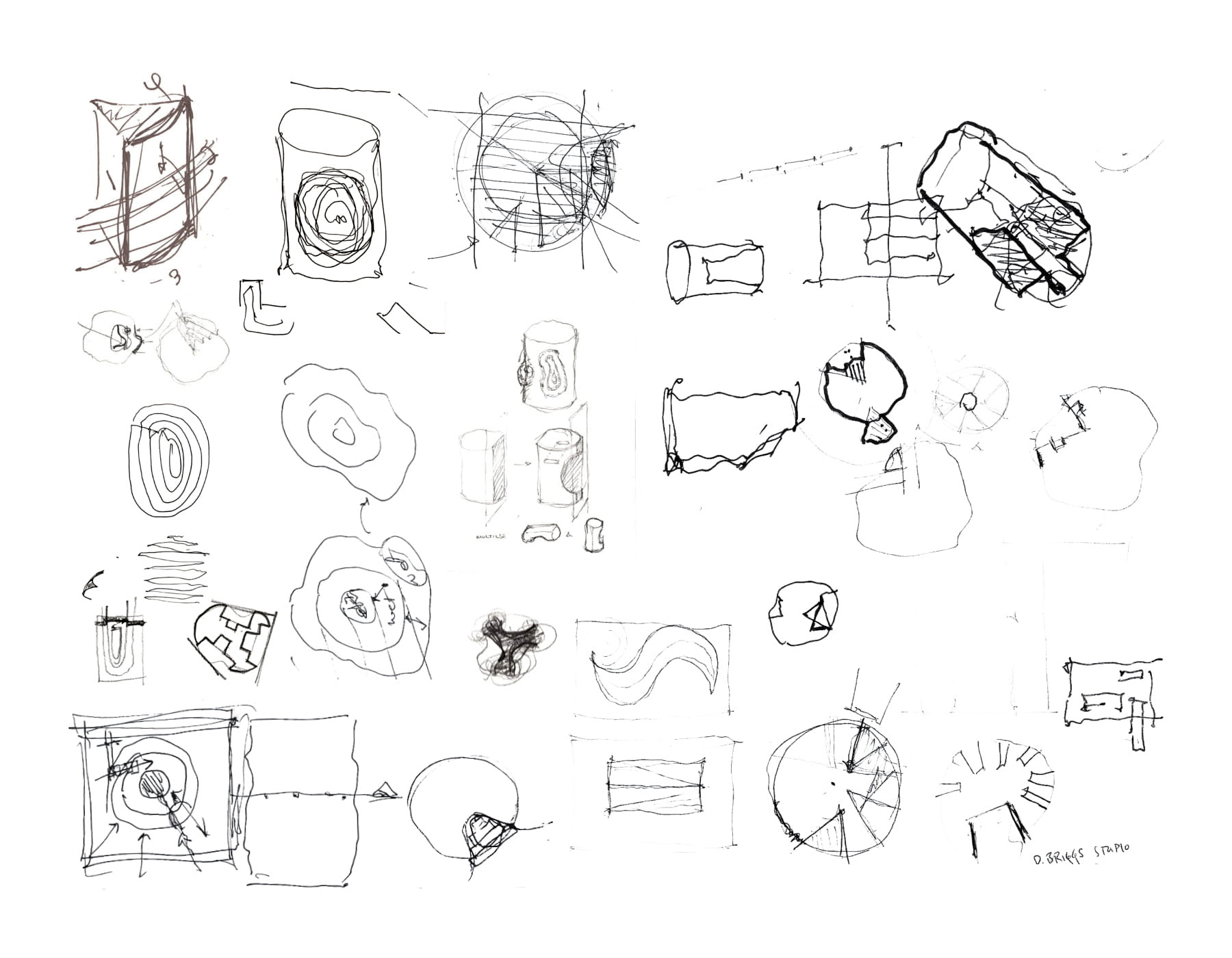
Collection of Sketches
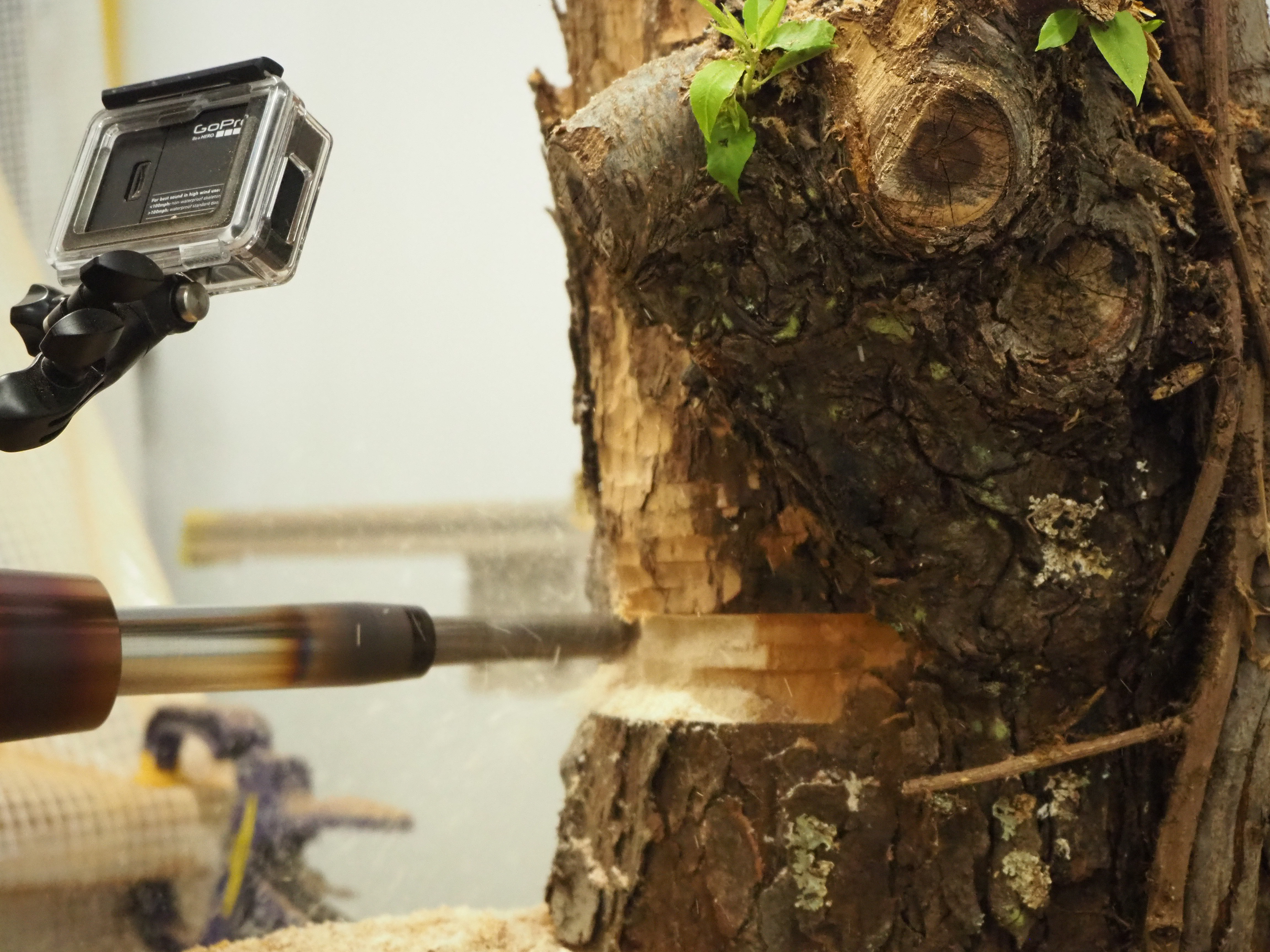
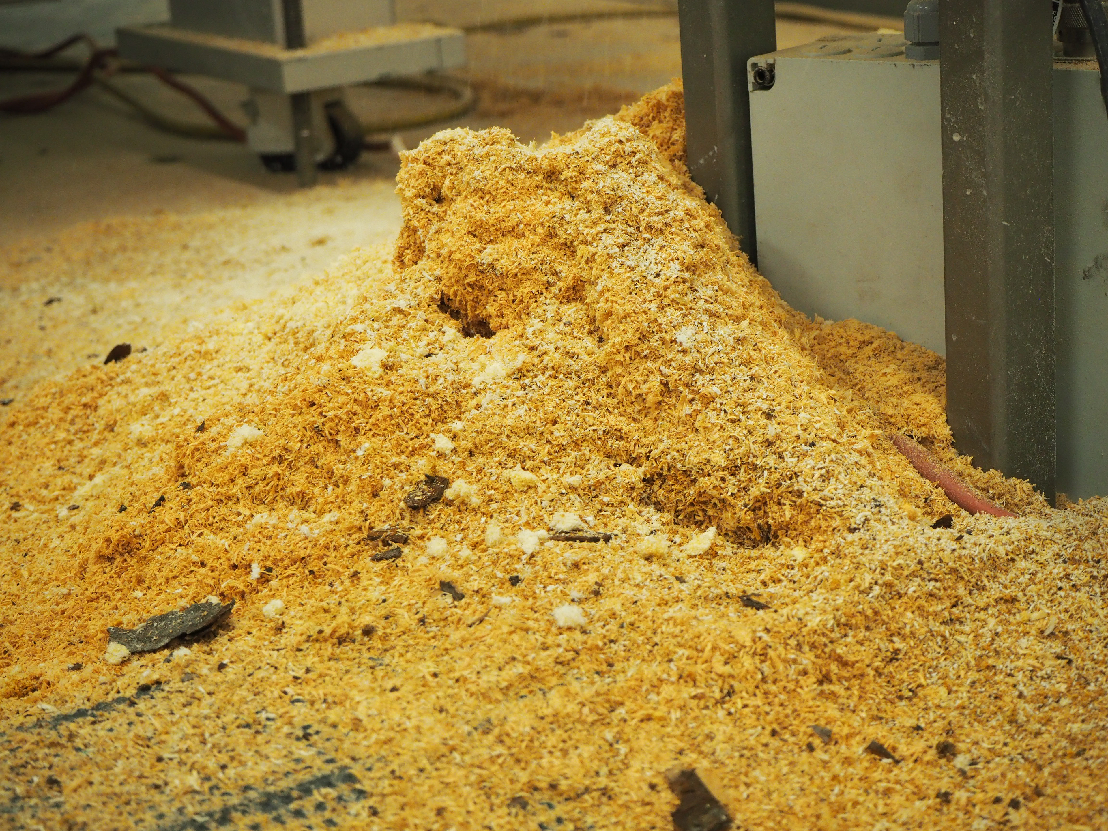
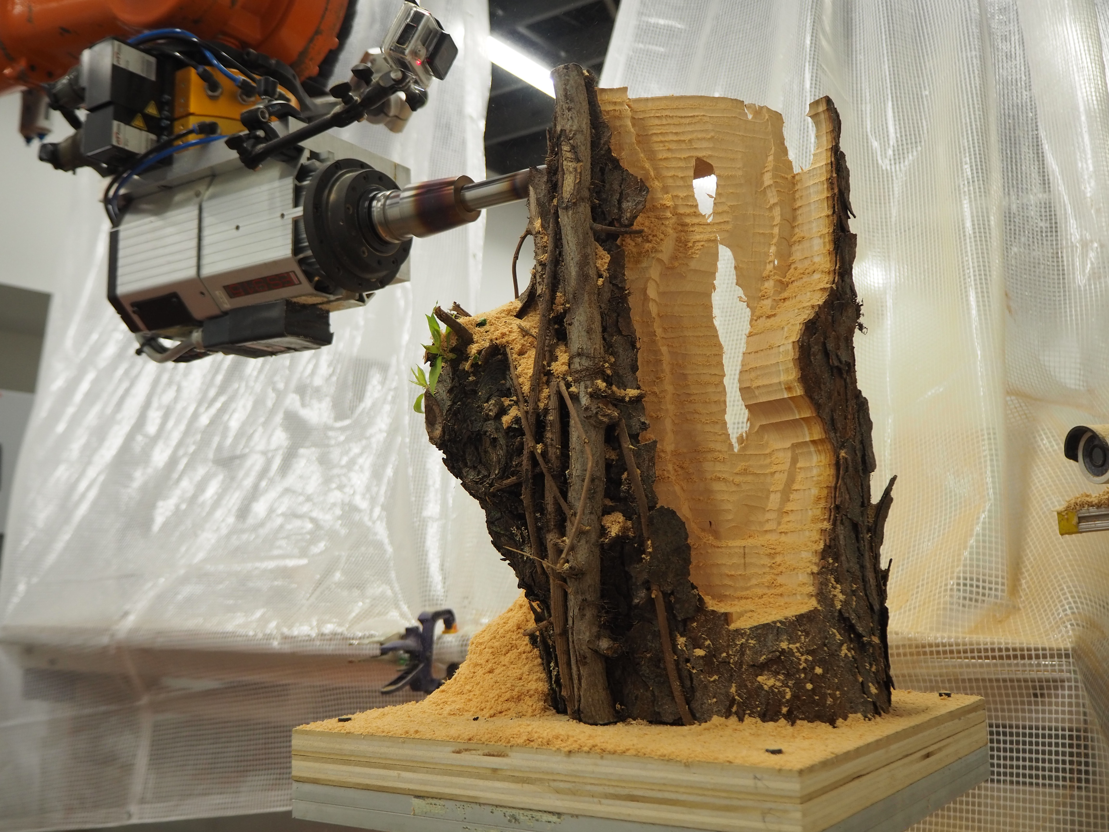
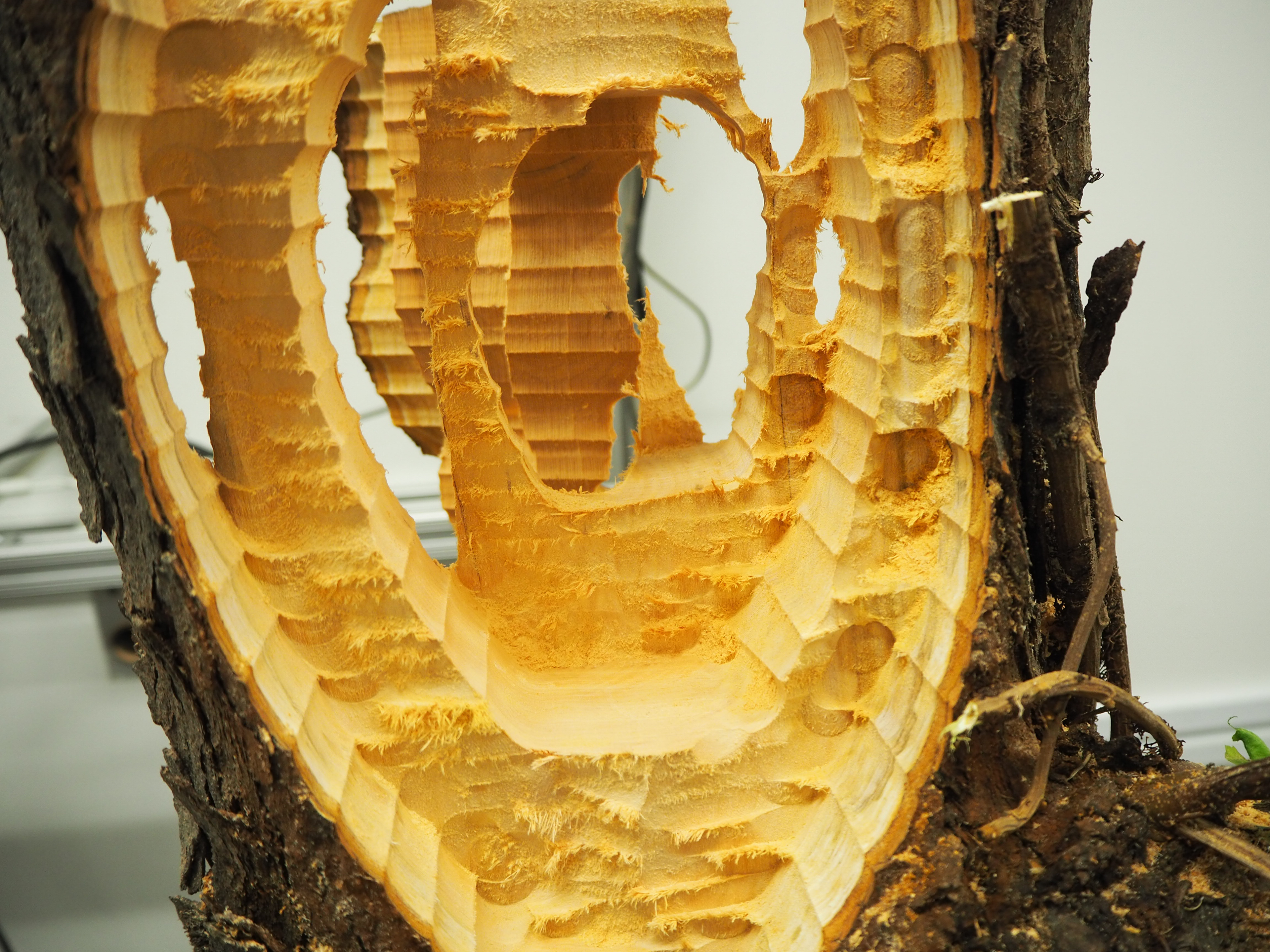
Final Piece/Images
Photography Credit: Kyle Bancroft
Photography Credit: Kyle Bancroft

Photography Credit: Kyle Bancroft

Photography Credit: Kyle Bancroft
Photography Credit: Kyle Bancroft
Photography Credit: Kyle Bancroft
Photography Credit: Kyle Bancroft
Photography Credit: Kyle Bancroft
Schedule
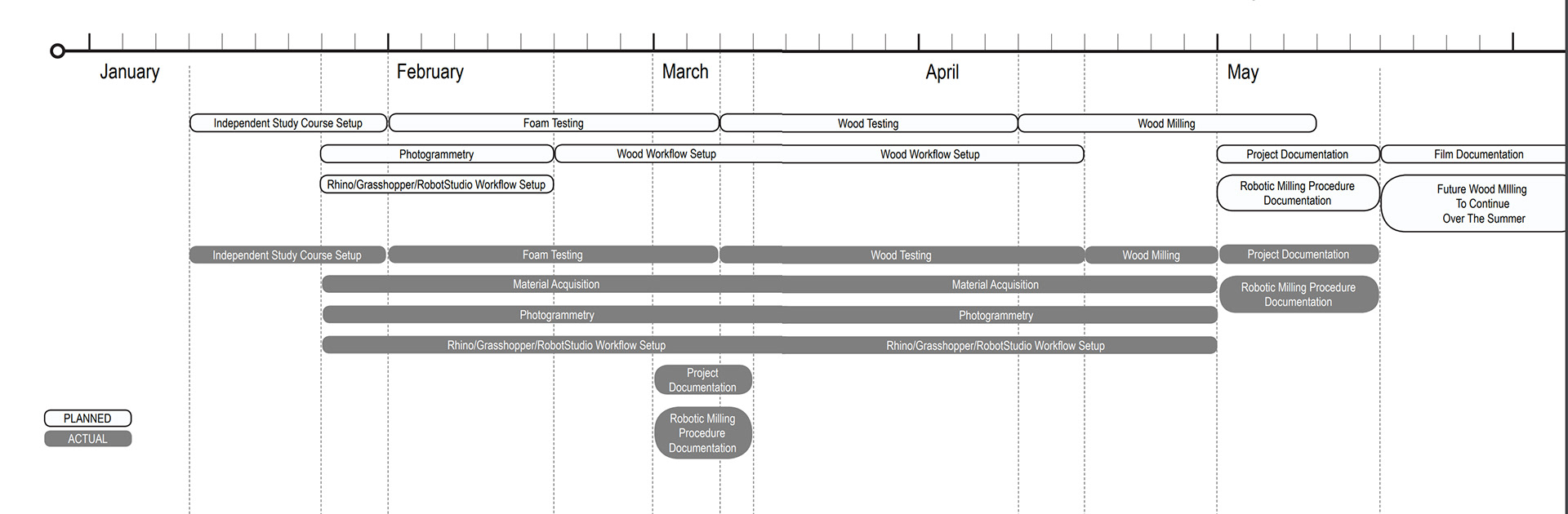
This proposed schedule, although aggressive, contains embedded opportunity to catch up on work that may be pushed back due to unforeseen challenges, but ultimately strives to develop a critical path to producing documentation of robotic milling processes and developing the infrastructure to do so at CMU through research and application. Looking back, it was clear that we couldn’t have accurately estimated how much time certain tasks would take given initial unknown factors such as our inexperience with robotic milling and scheduling conflicts.
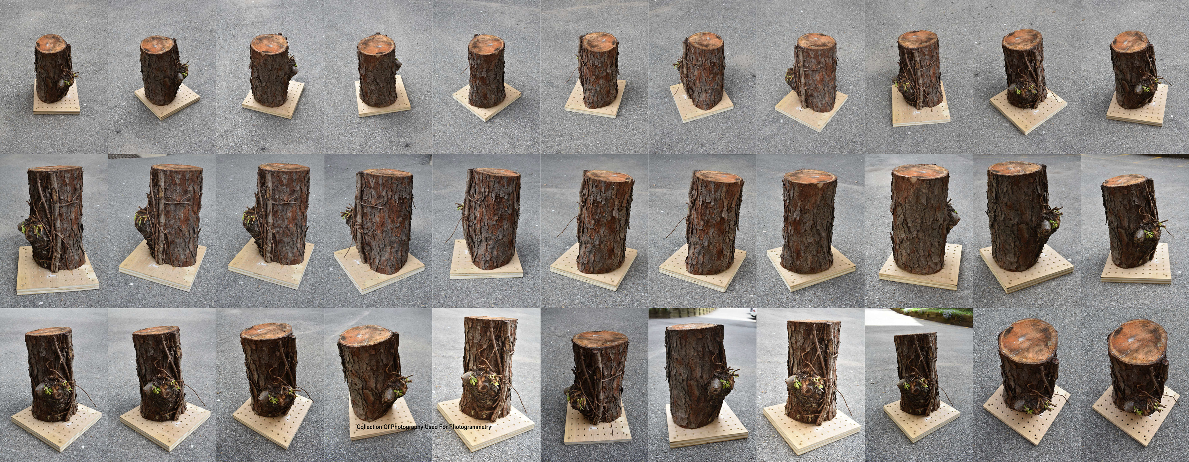
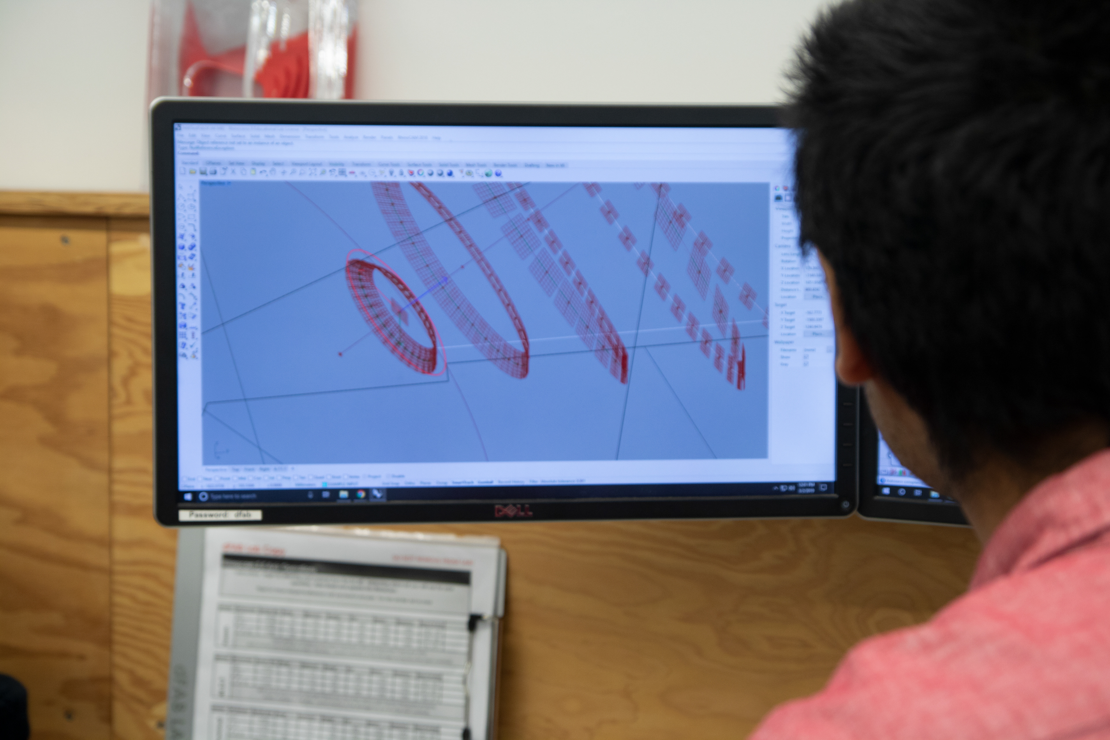
Photogrammetry
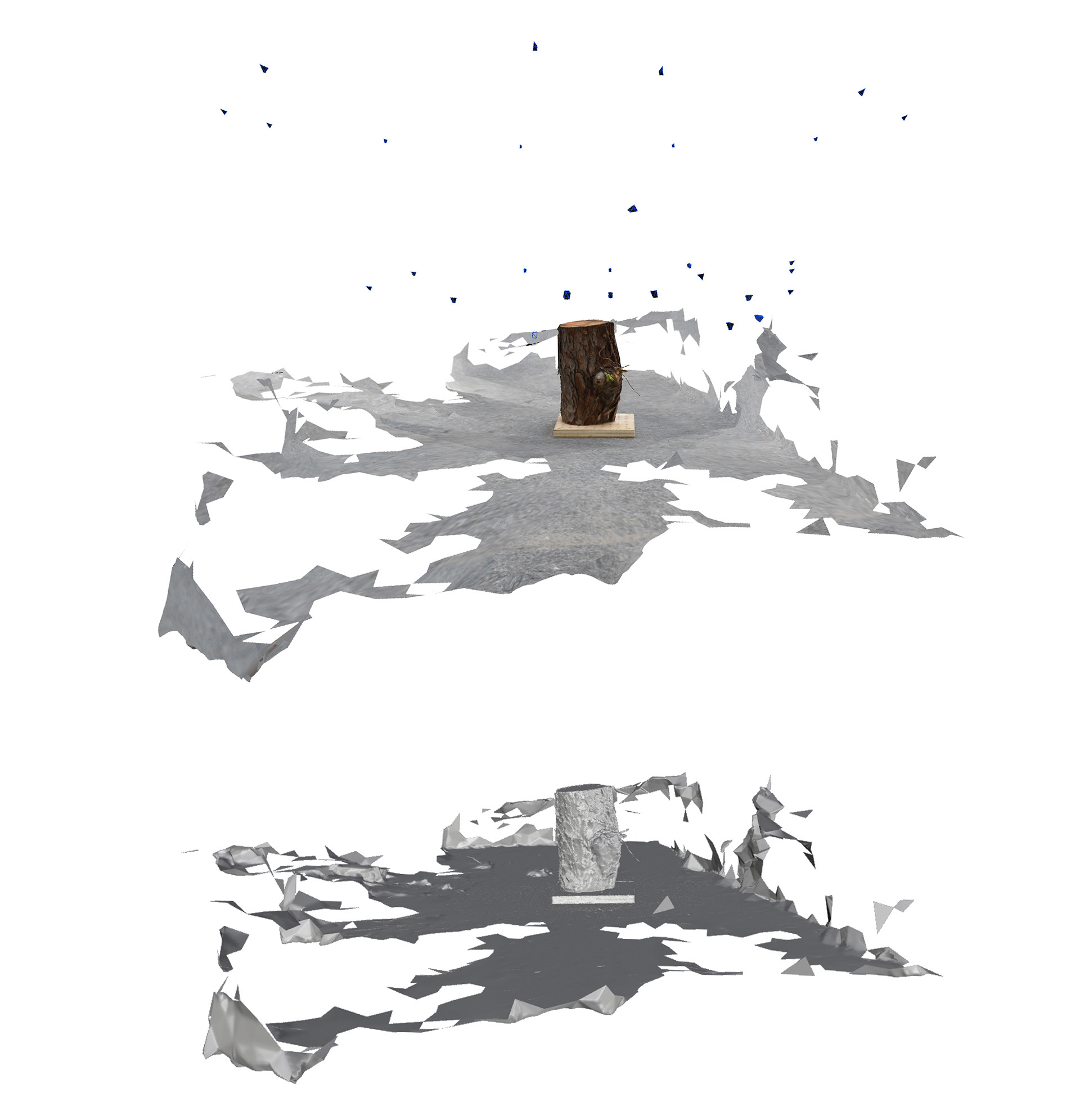
The project has decided to utilize the photogrammetry software 3DF Zephyr to begin understanding and testing different methods and ways of executing photogrammetric processes. The software is free, albeit with some limitations in regards to the allowable number of photos input, and offers interesting features that allow a user to make more efficient their photography in achieving a higher quality scan. We are looking to explore how photogrammetry can augment the level of precision of our work with as found materials as they may range in size, texture, and volume because they are not standardized. This will become the first step in our process for milling as-found materials and will allow for greater efficiency in milling. While the first test is quite rough in quality, the lighting environment, photographic content quantity, and camera quality will be increased for later iterations which will produce a finer resolution model to work off of. This can be seen in the images shown on the following pages which portray a higher quantity of base imagery for the software to use and the resulting increased accuracy in 3DF Zephyr and Rhinoceros as textured meshes. Photogrammetry became absolutely critical in regards to safety, efficiency, and design. For safety, modeling based on an accurate model of the log helped to inform us as designers where the milling bit would be taking out material. In terms of efficiency, as the model got more accurate we were able to be more aggressive with tolerances and operations that were implemented for safety. Lastly, the photogrammetry model allowed us to know exactly where we were taking out material so that what we modeled in Rhinoceros would be the end result of running the code that we generated.
Crucial to ensuring accuracy in our digital model was the securing of the trunk to the workholding plank further explained below. While the software was able to calculate the precise form of the trunk, it did not scale it correctly and so having a specific point of reference to scale the model was crucial. In addition, the base allowed us to locate and position our trunk on the rotary table correctly in preparation for milling so that there was less room for error in ascertaining which side we were milling.
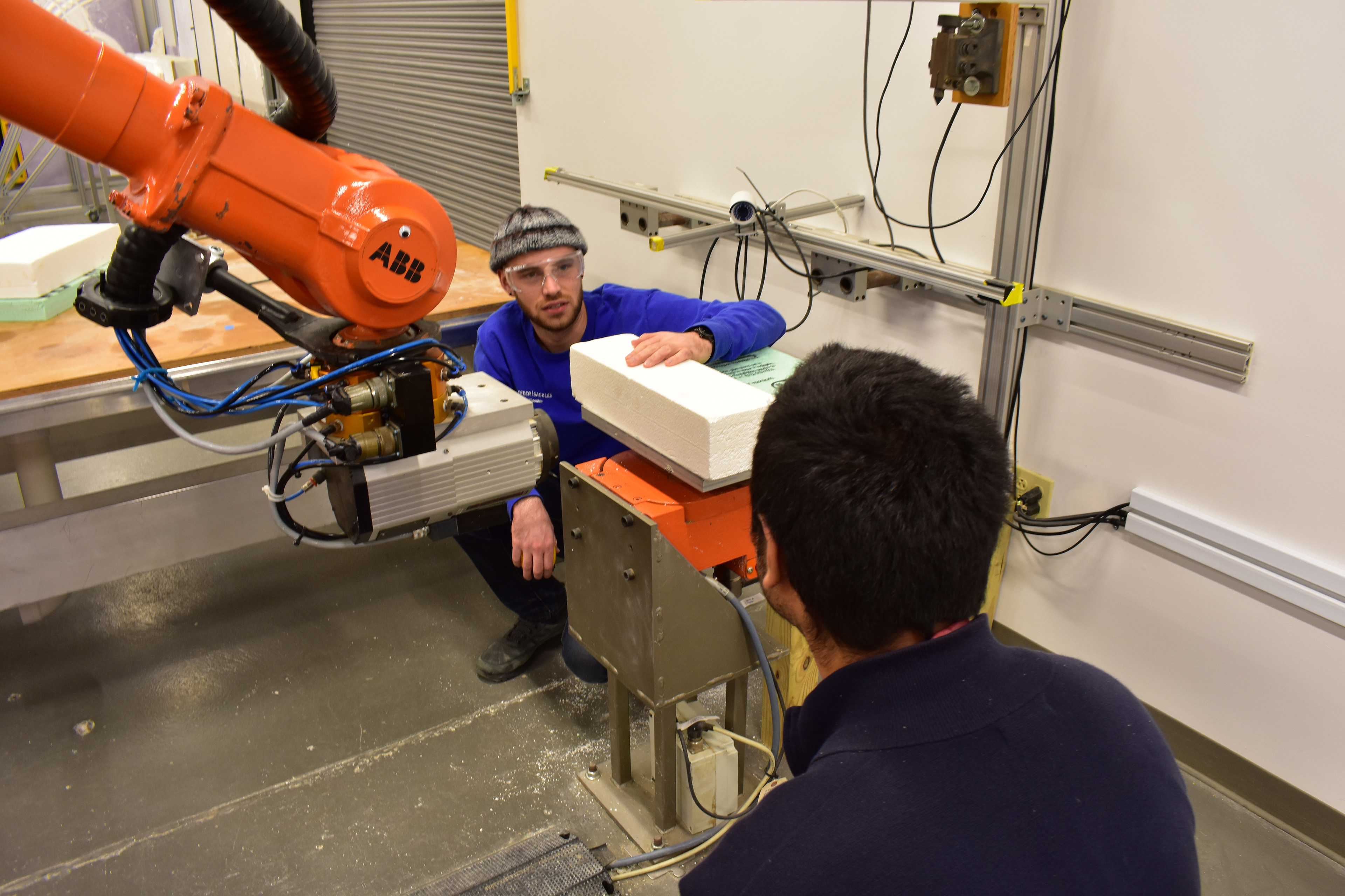
Foam Milling Workholding
When working with foam, the rotary table as a resource is invaluable both in regards to the freedom of rotation it affords which overcomes many issues that may arise with orientation and the physical limits of the robotic arm. Furthermore, the rotary table also functions as a simple means of workholding as it also doubles as a vacuum table. For more simple procedures in which there is little risk in damaging the material, it serves well to limit the complications of keeping the material in one place. Thus, for all of the foam milling procedures, the vacuum rotary table functions well in securing the material firmly.
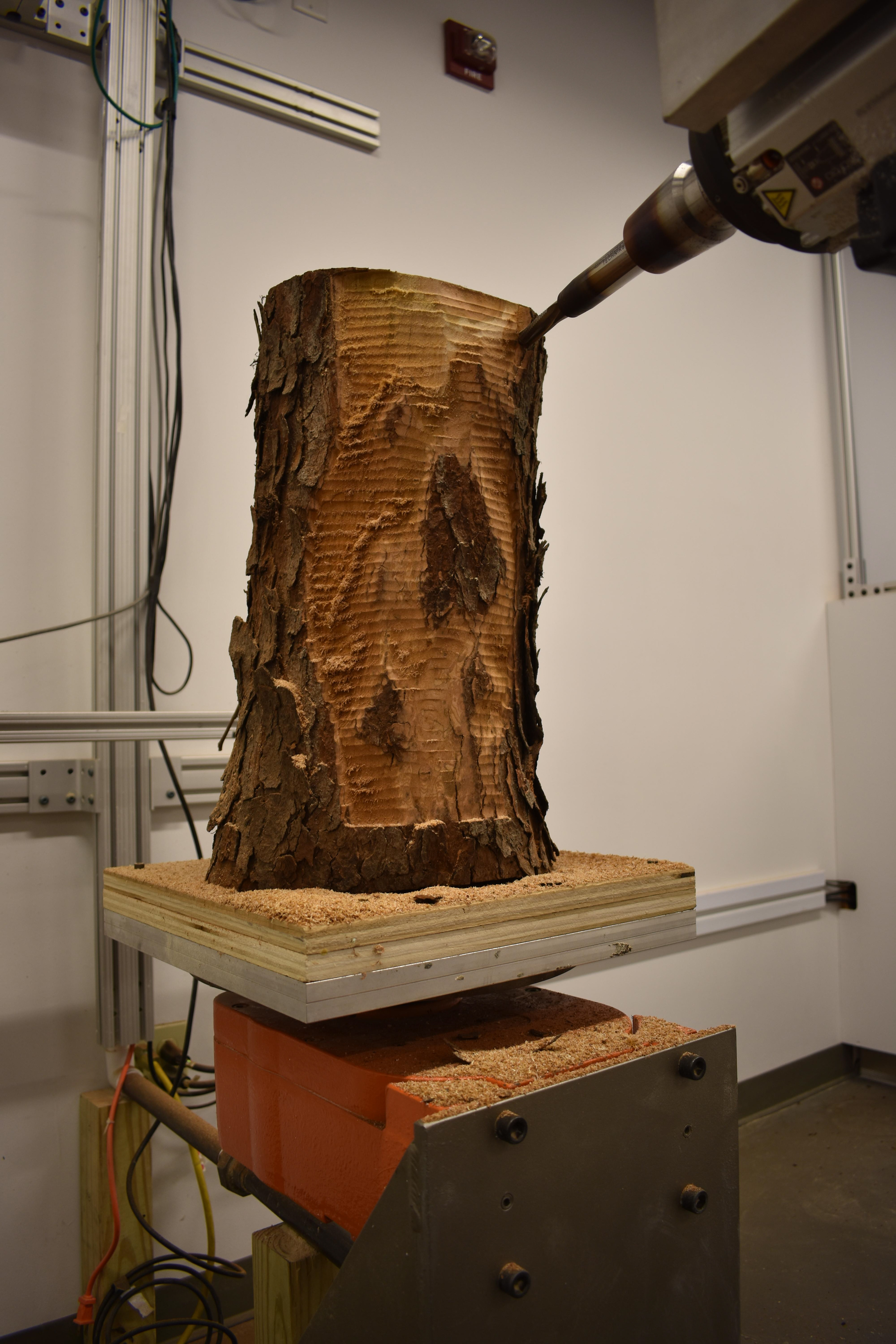
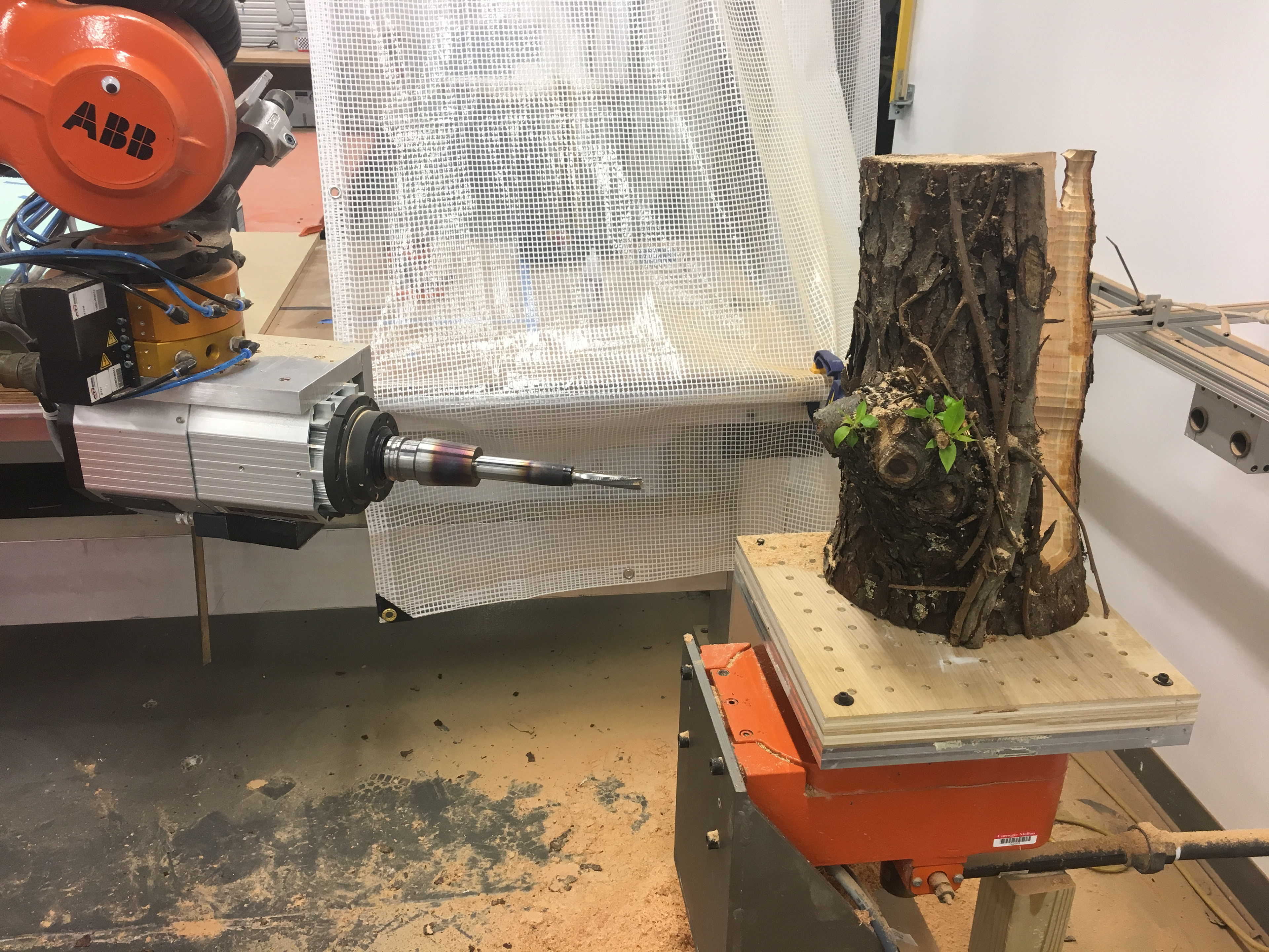
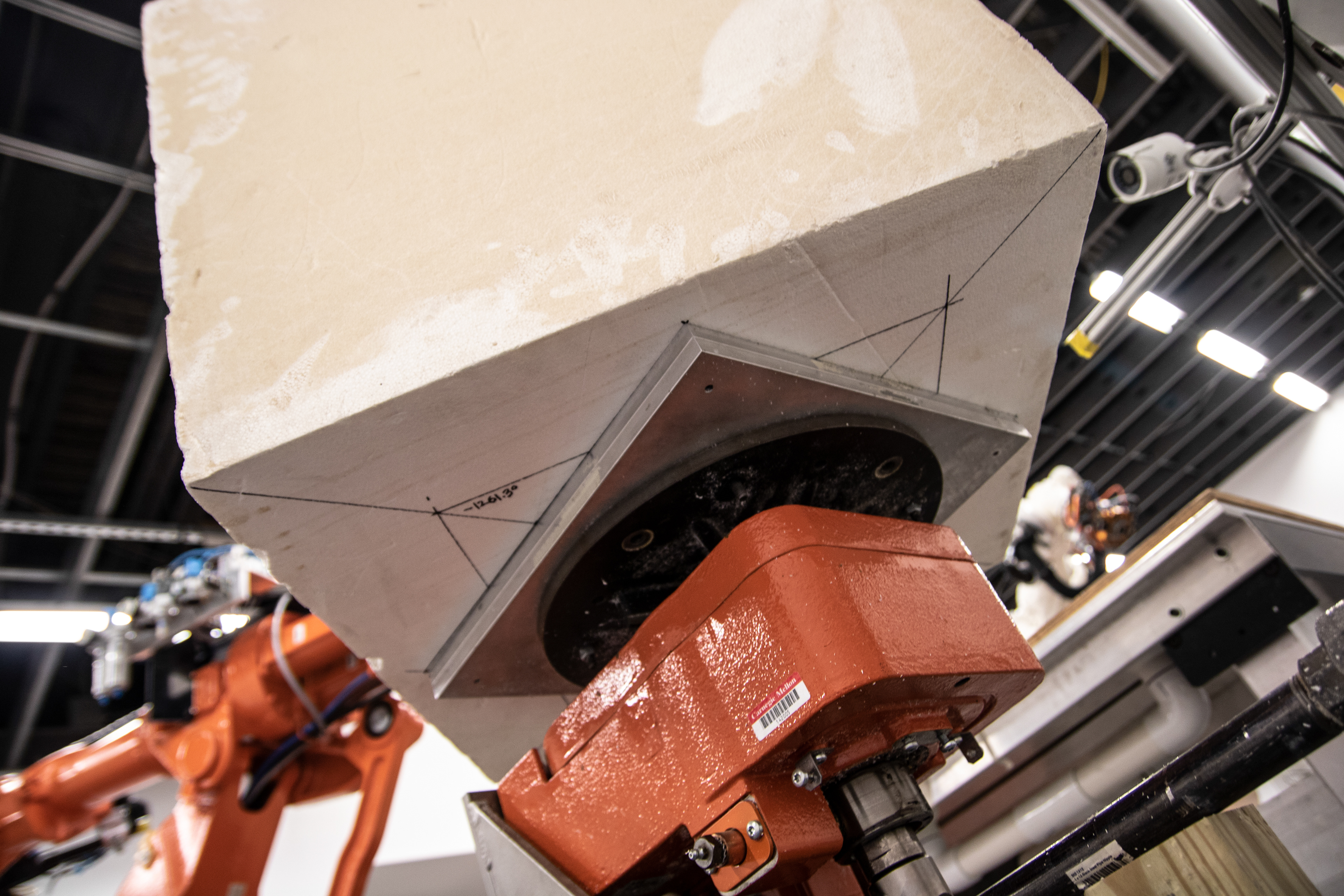
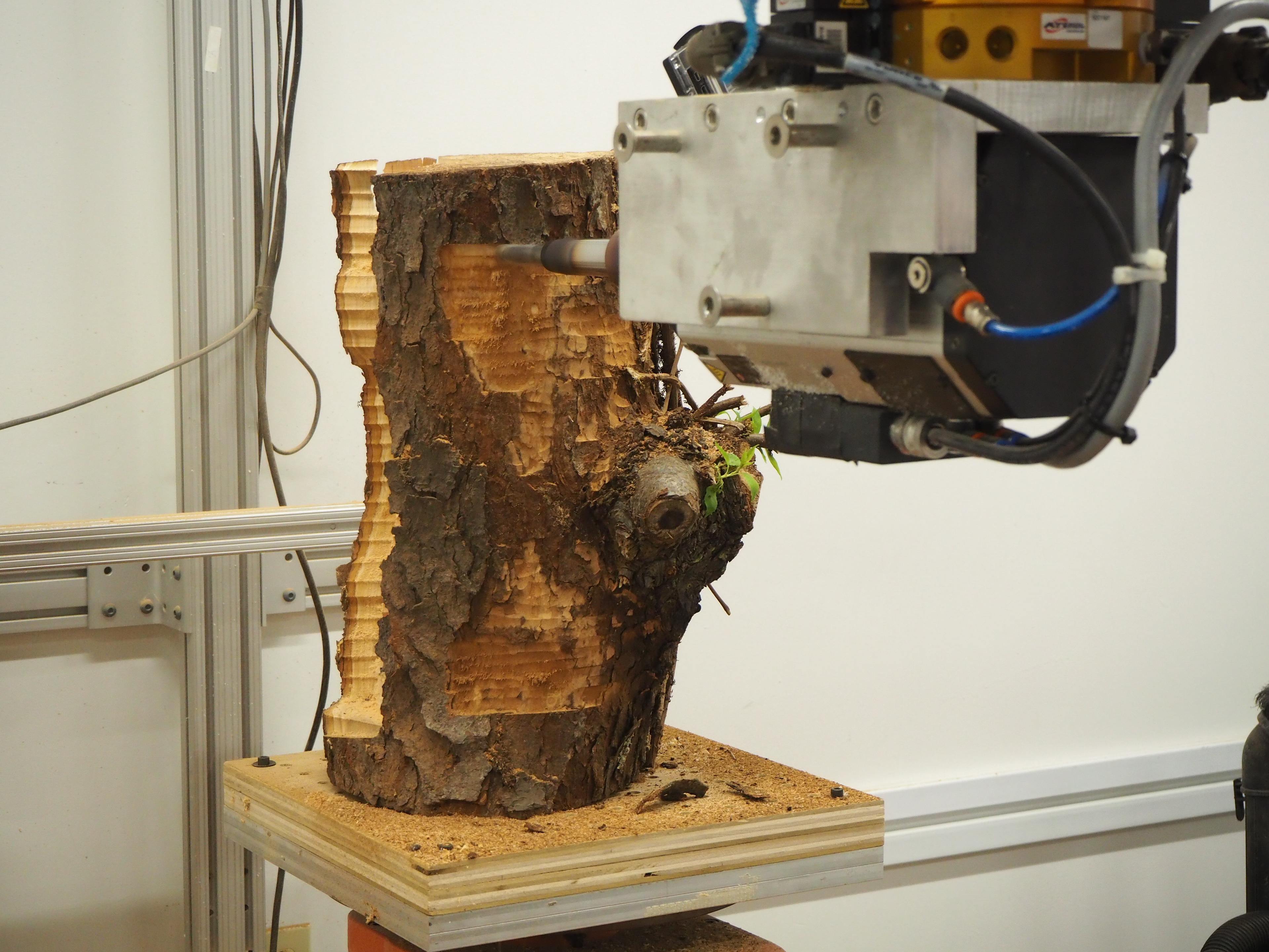
Wood Milling Workholding
When working with the wooden logs, the rotary table was indispensable both to hold the logs down, and also to gain an understanding of the position and orientation of the logs made possible in conjunction with the photogrammetry model. We were able to orient the log when working with various faces by using the table as a coordinate system to serve as a reference point for which face we were milling. Critical to this was the designing of a simple and functional workholding mount which was a 14.5” square piece of plywood which had holes drilled into it. This piece allowed us to lag bolt the log into the mount and bolt both to the rotary table, securing it in place. This more simple method allowed us to secure the log, but other measures could have been implemented to secure the log further. Given the formal moves we were making, however, we decided to use this method which, towards the end when a lot of material had been milled out of the log, made sequence of toolpaths important. For example, milling was done from top to bottom to make sure that more material was secure and that the log would not vibrate. While more intricate workholding methods could have been applied, this method was more than enough for this exploration.

Foam Milling Toolpath/Simulation
The project iterated through tests by focusing on cuts and formal moves that were anticipated to be used in milling wood. In testing these procedures on foam, we were able to greatly reduce the risk of the tests while building upon our carving tools to be later applied to milling wood after ascertaining what is possible. Critical to the success of this project is running through the various simulation checkpoints both digitally and physically. After generating code, extensive simulation would be done through Grasshopper/HAL as well as RobotStudio iteratively as needed.
Wood Milling Toolpath/Simulation
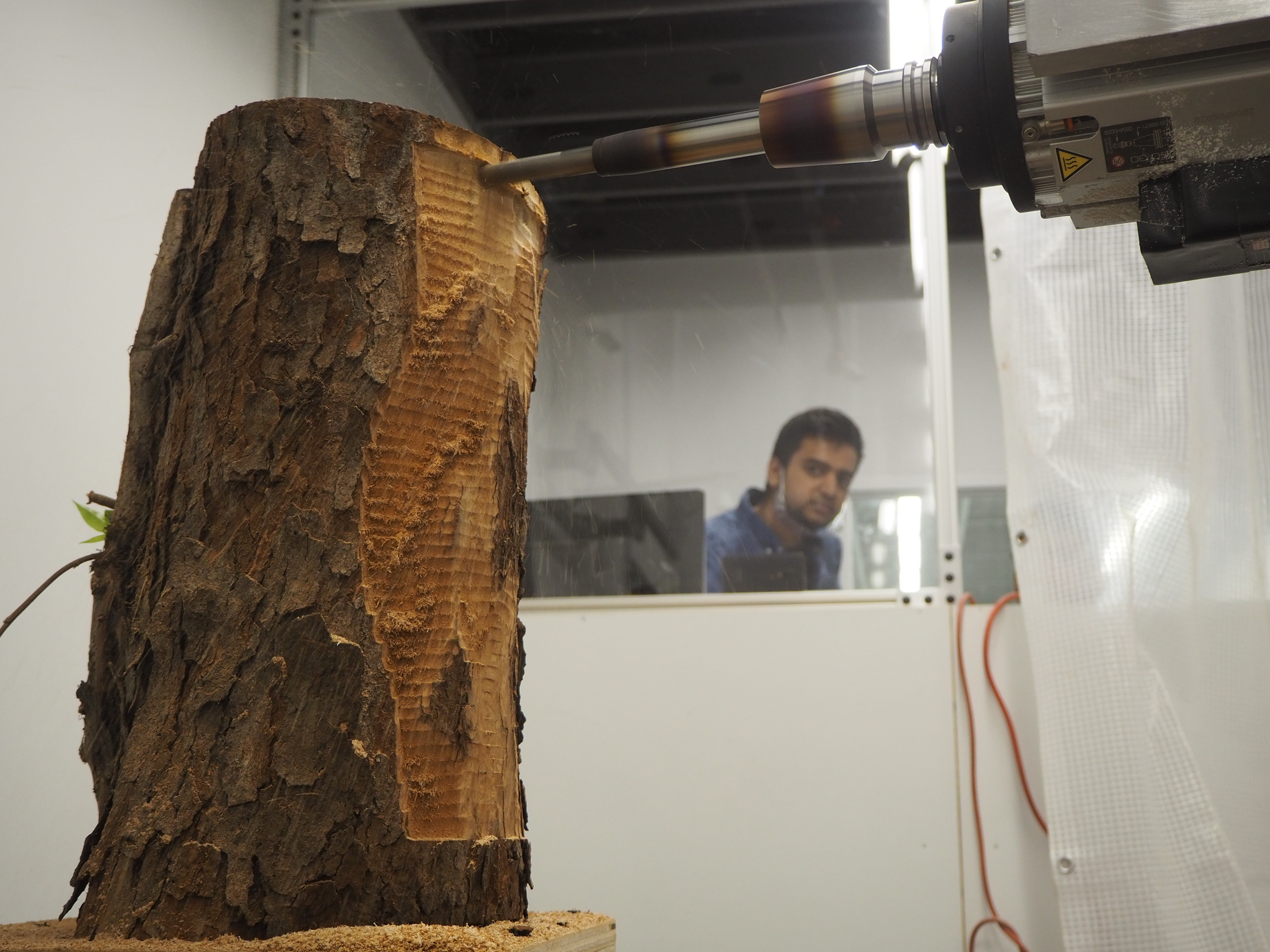
As we moved into wood milling tests and runs, we started by milling out a straight line in a test piece which allowed us to get a feel for the feeds and speeds that would cut through the material safely. We began with the highest RPM that the spindle could output and used a slow tooling speed and small plunge which was gradually increased as we felt more comfortable. This, as previously mentioned was changed to adapt to various situations where there was more or less points of concern. One of the biggests changes that we faced was the difference in length between the milling bits used for foam and the ones used for wood. We found that the wood milling bits were much shorter and this drastically changed our approach to this project and how we would be milling the logs. We embraced these constraints however, and allowed them to drive our explorations and design mentality.
Foam Milling Execution
The procedure of milling foam varies based upon the complexity of the toolpath intended. For simple cuts, a test run would be executed without the foam installed on the rotary table, then if no issues arose, the foam would be installed and the procedure would be run again. For more complex cuts, the process varied. In some cases, the toolpath would be run without the milling bit, but in other cases to better understand what was happening, the procedure would be run with the material and the running milling bit installed. In all cases, the test run would be done at a much slower speed for safety and to allow for more time to identify any potential issues.
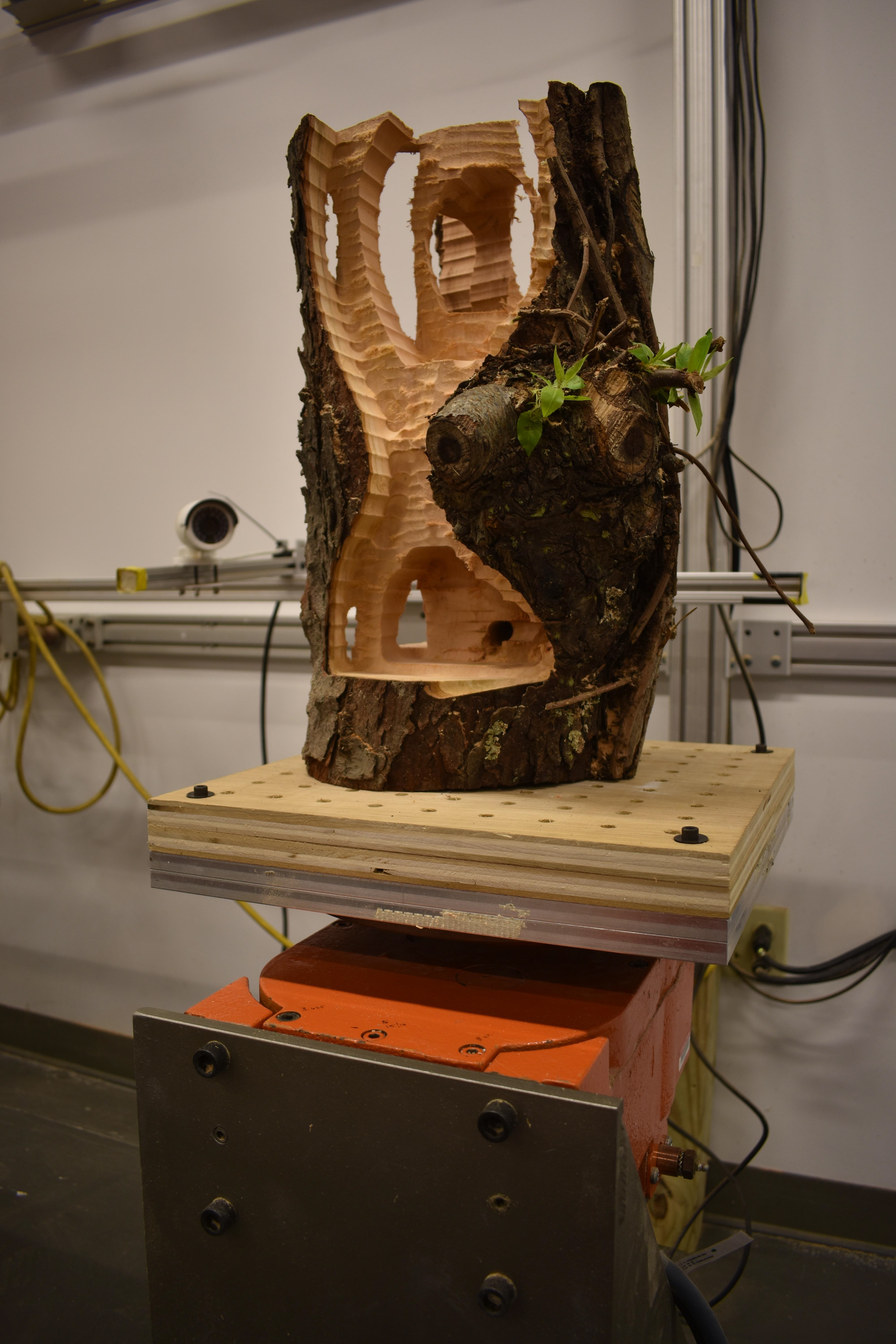
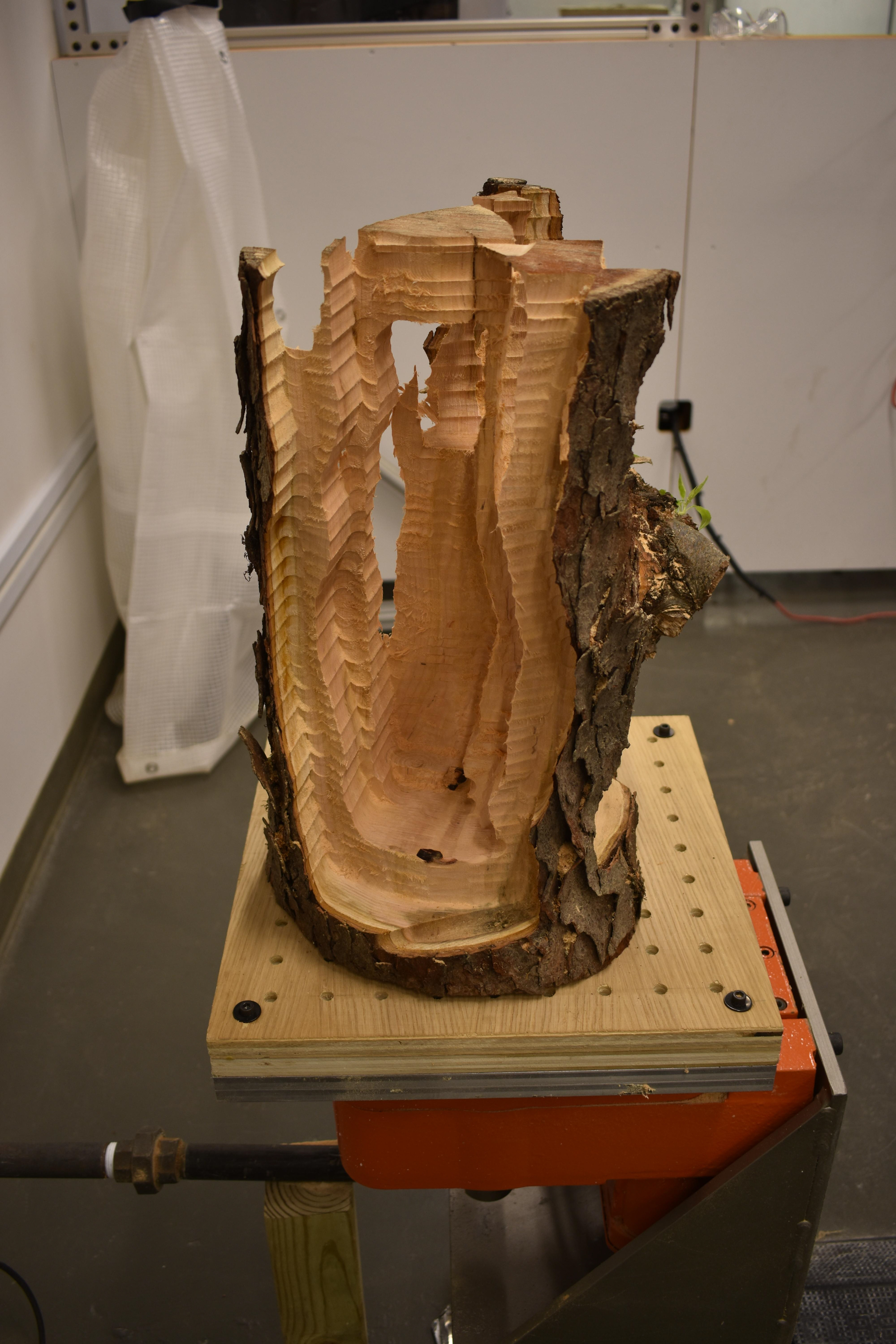
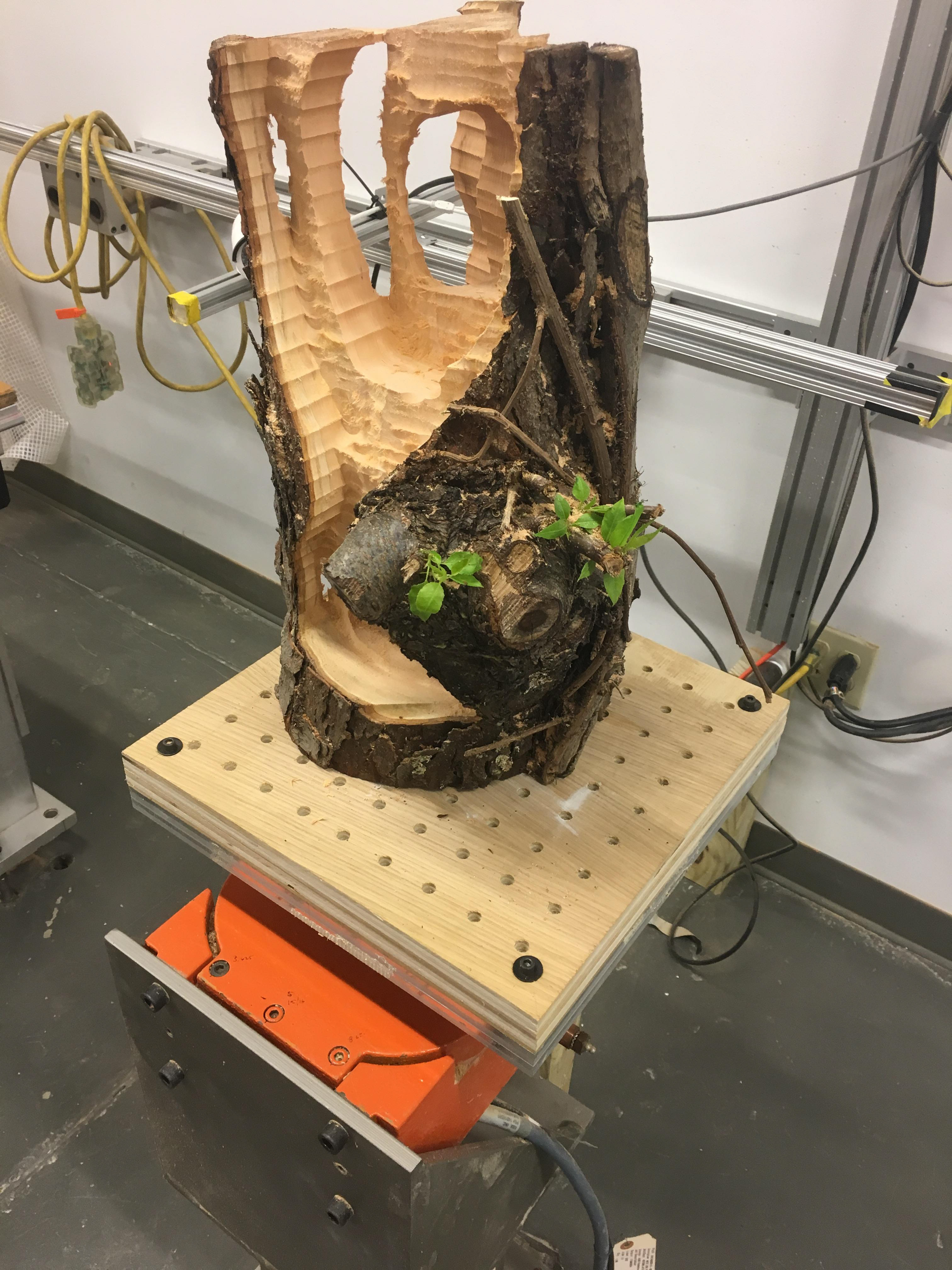
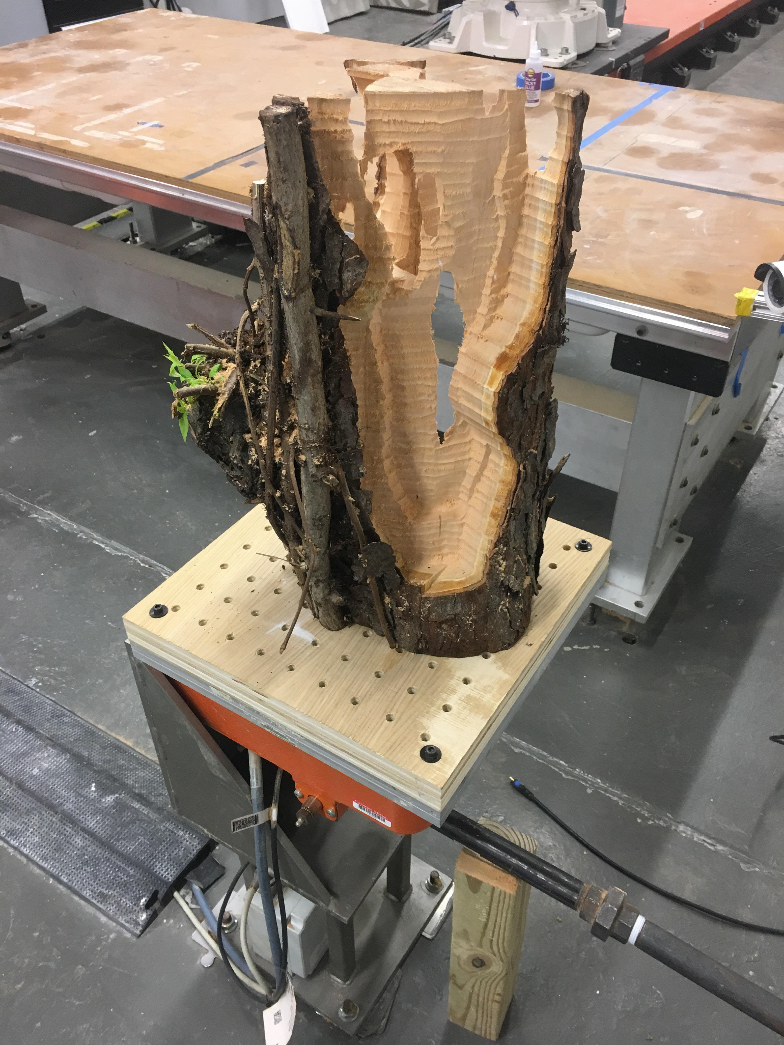
Wood Milling Execution
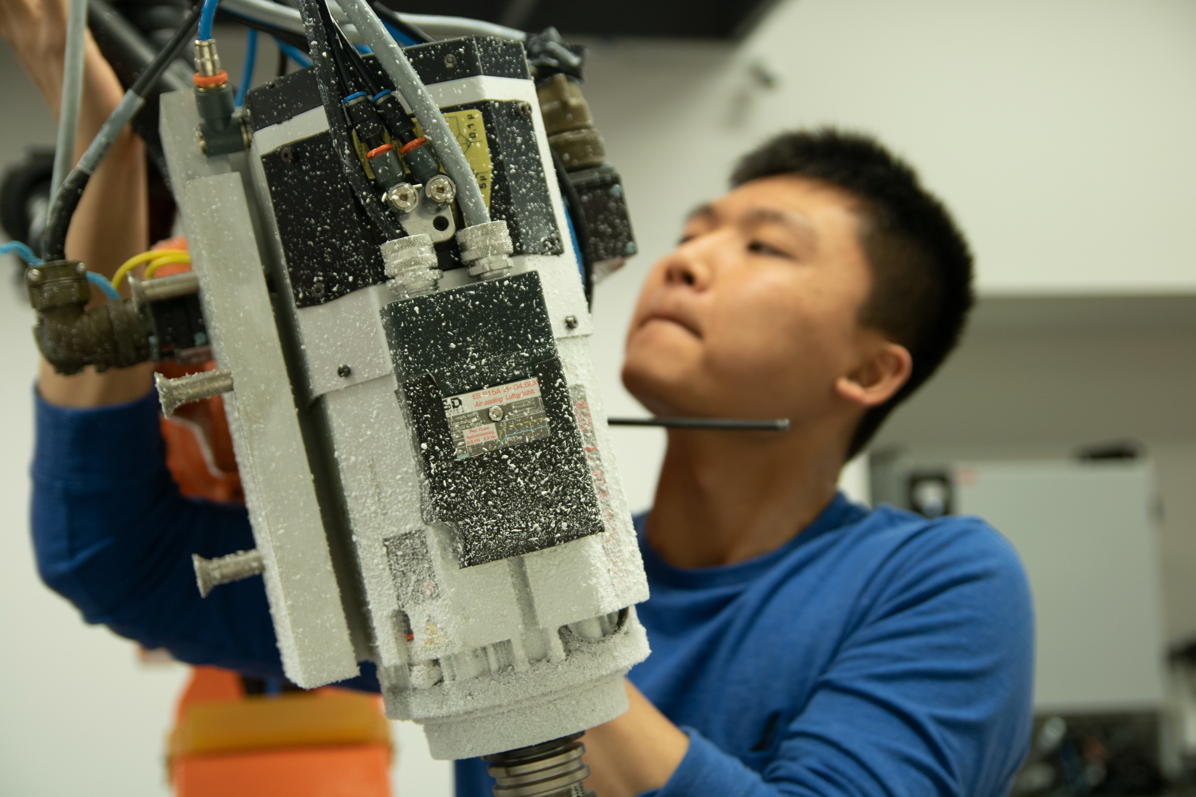
As the main concern for the wood logs was weight, most of our explorations revolved around how we might carve out larger chunks of material in a manner that responded to the material as well as to the function of a stool. We experimented with a variety of strategies and applied the formal conditions that we had explored through foam, putting them through the lens of a very different material both in how it reacted to the milling bit and what flexibilites it did or did not offer. When executing we split the roles to take advantage of our team’s numbers to efficiently and safely execute toolpaths. Generally, we had one individual assigned to operating the robot, one to documenting, and one to keeping tabs on the dress pack. This allowed us to sight issues as soon as possible and communicate to avoid any problems.
Foam Milling Feedback Loop
For more complex operations, we ran into issues which forced the group to return to RobotStudio or even backtrack to Grasshopper/HAL to troubleshoot and propose solutions. Most often, issues arose with the positioning of the dress pack and the limitations of joint rotations which either were resolved physically, or reorienting the toolpath, or spliting up the procedure into multiple parts.
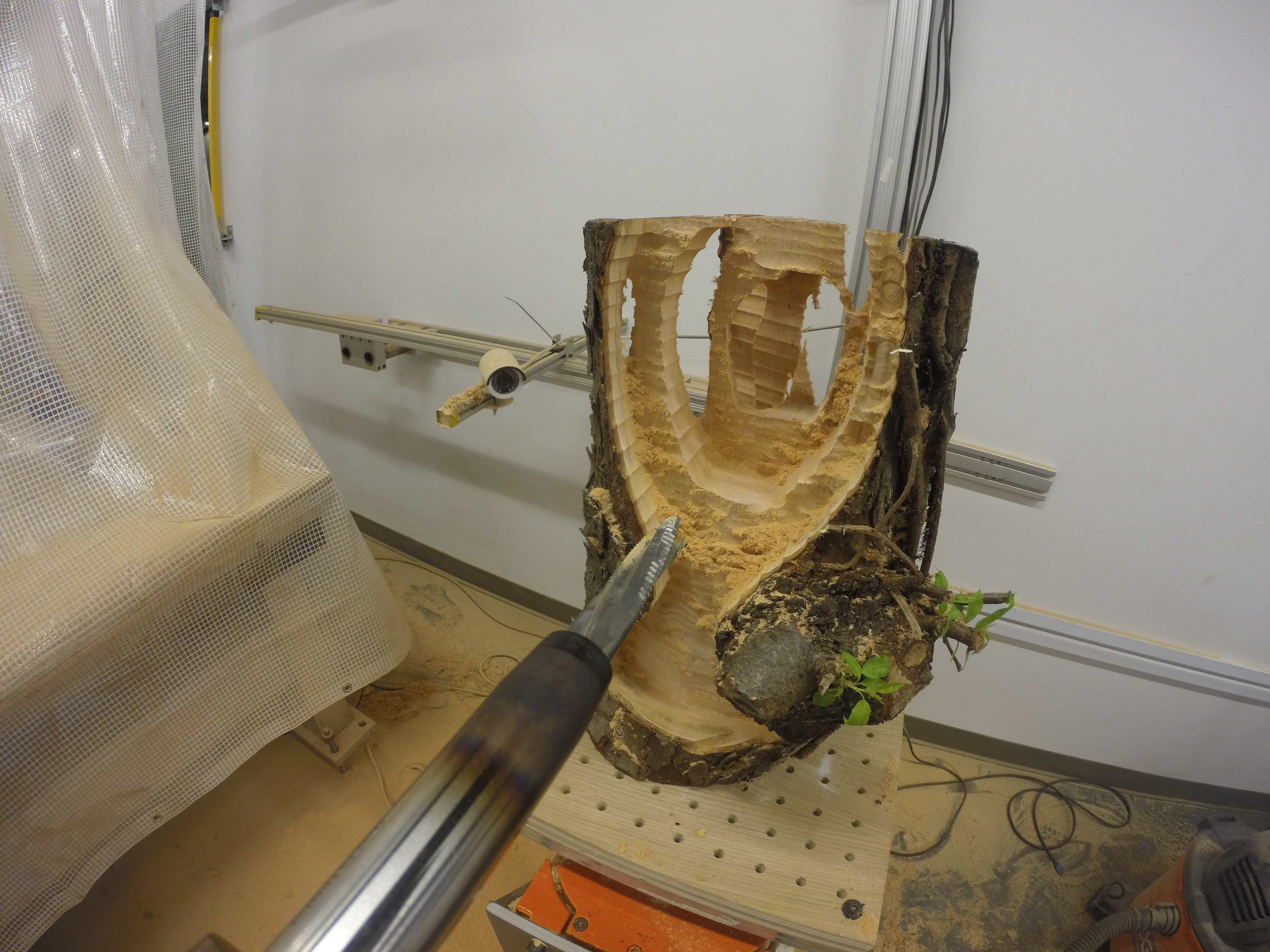
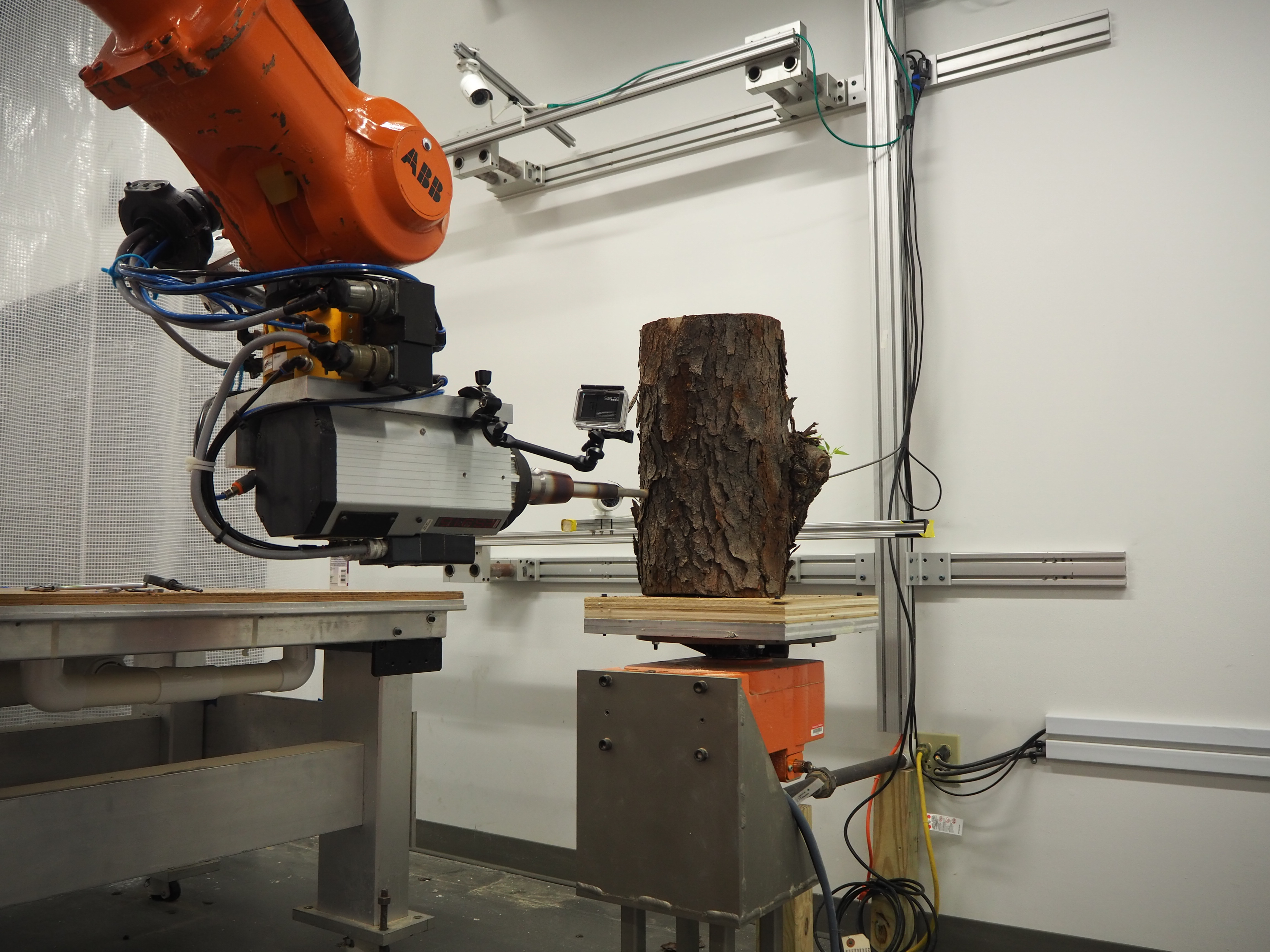
Wood Milling Feedback Loop
Although our procedures were relatively simple, we were constantly concerned about the dress pack of the robotic arm. As such, there were often times when we had to rotate the log 45 degrees, or find other solutions to make sure that the robot did not destroy the dress pack, or reach an error point. As such, we kept a careful eye on the robot at all times, but took special precautions for the first layer of cutting, as it generally would show if issues would arise.
Sketching/Formal Moves
Looking forward, we felt it was important to compile some of the formal techniques that were left unexplored as well as compare them to the ones that we delved briefly into. Using this study as a jumping off point, there is much to be done both in the formal realm, but also in the realm of taking extreme care in designing a stool as a function object, but also one that exemplifies the use of a raw, natural log that has been whittled away by a hyper accurate robotic arm.
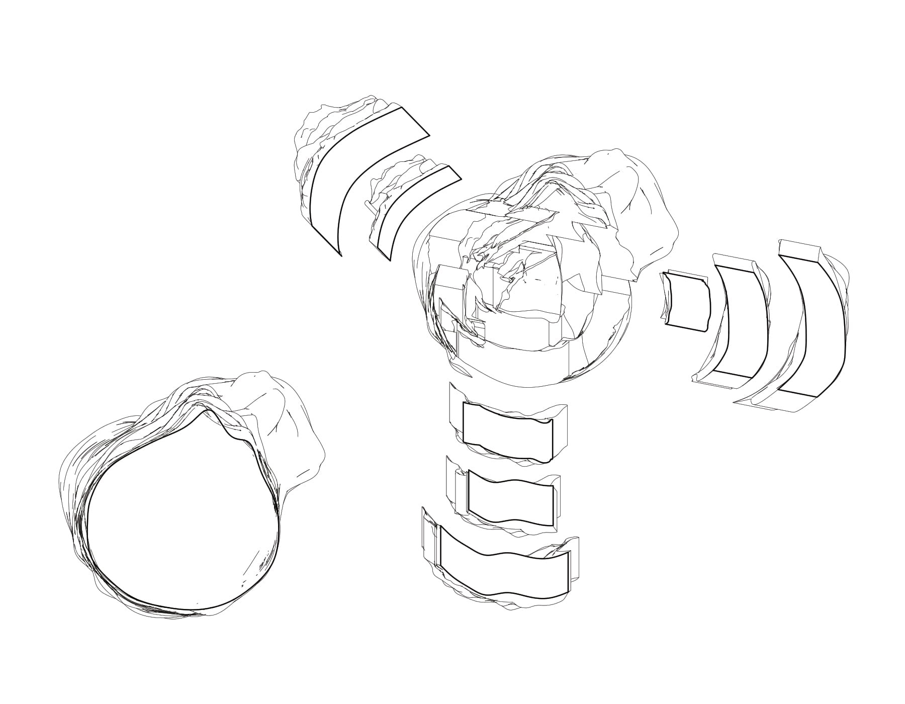
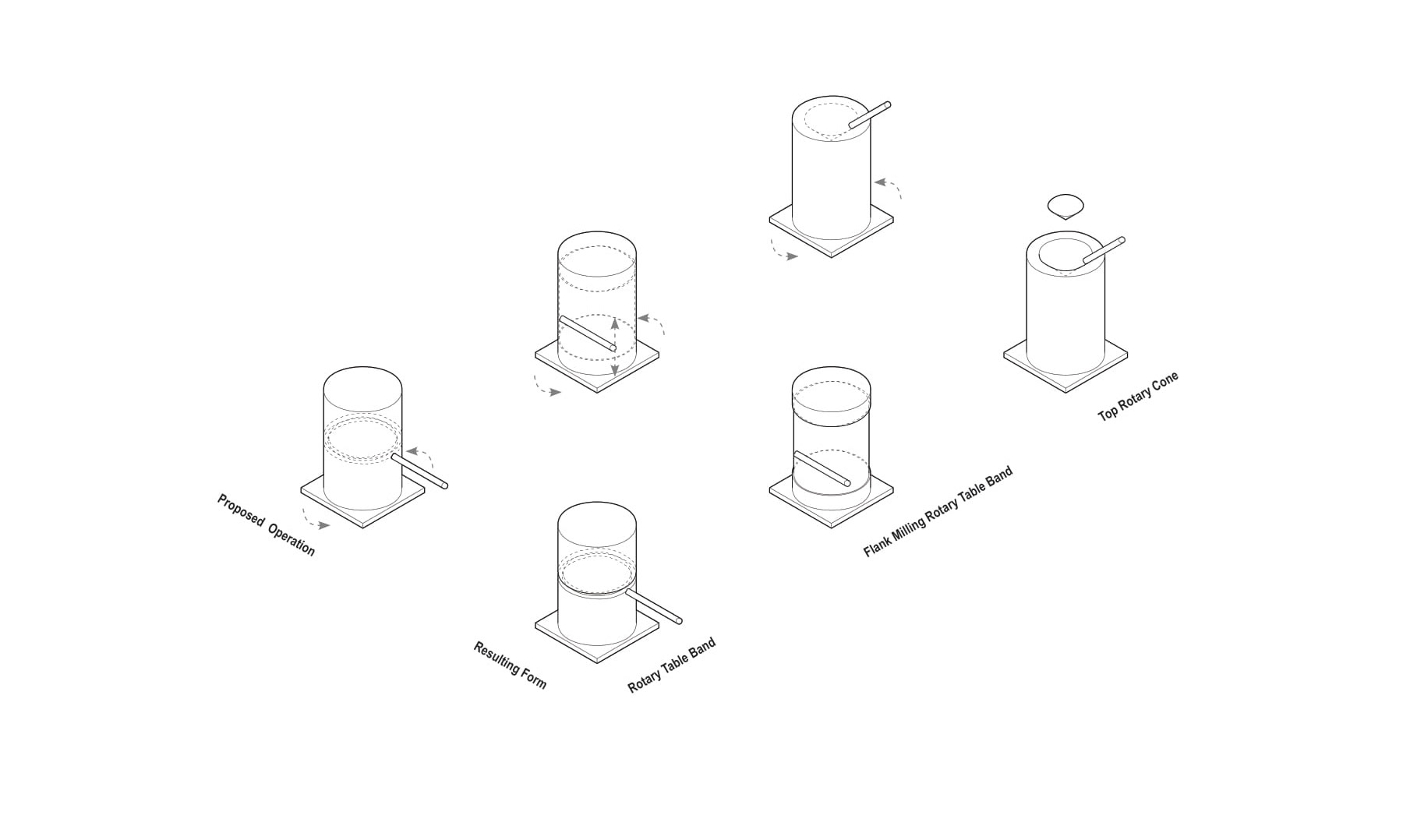
Plans (Top & Exploded with Removed Material)
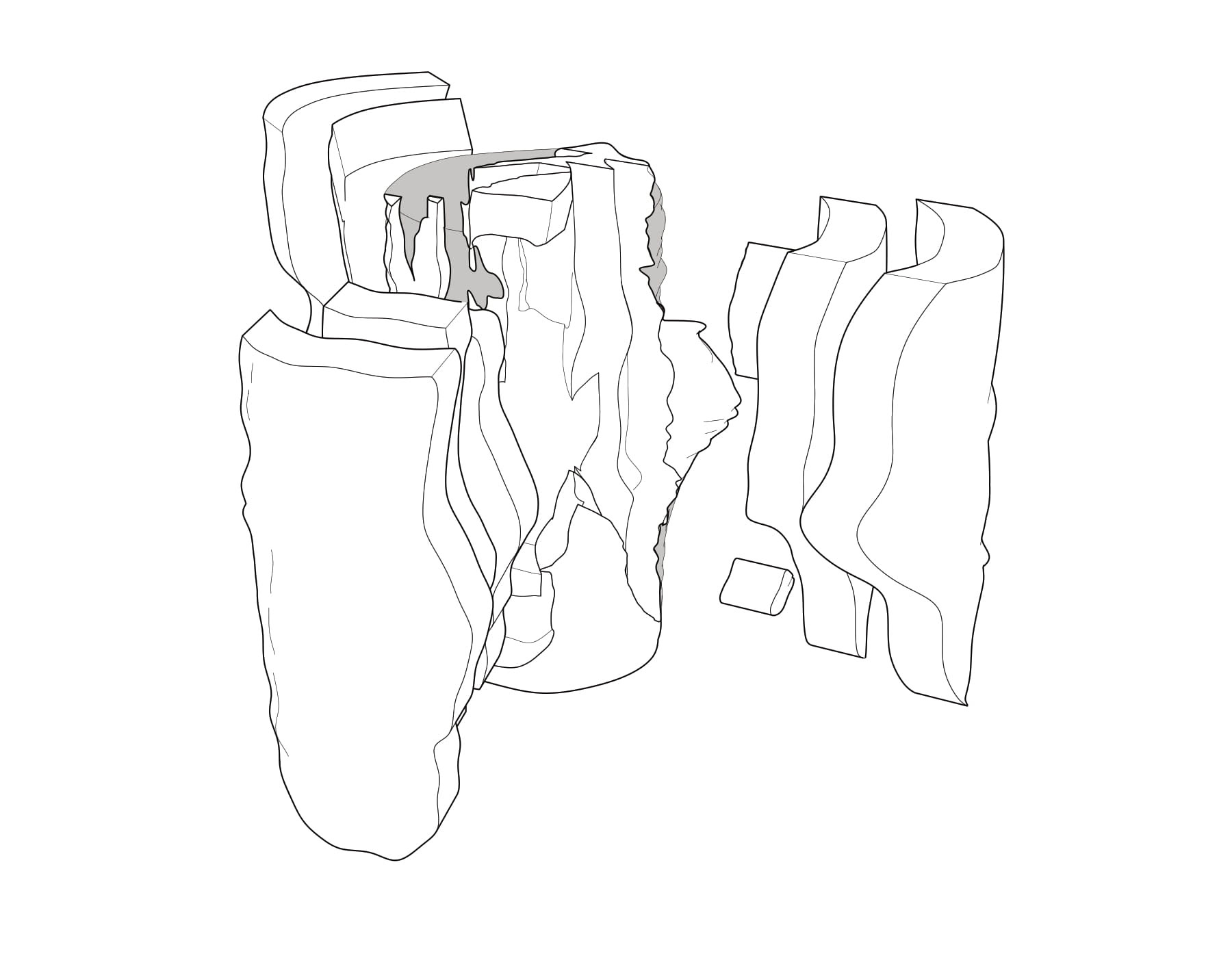
Exploded Perspective
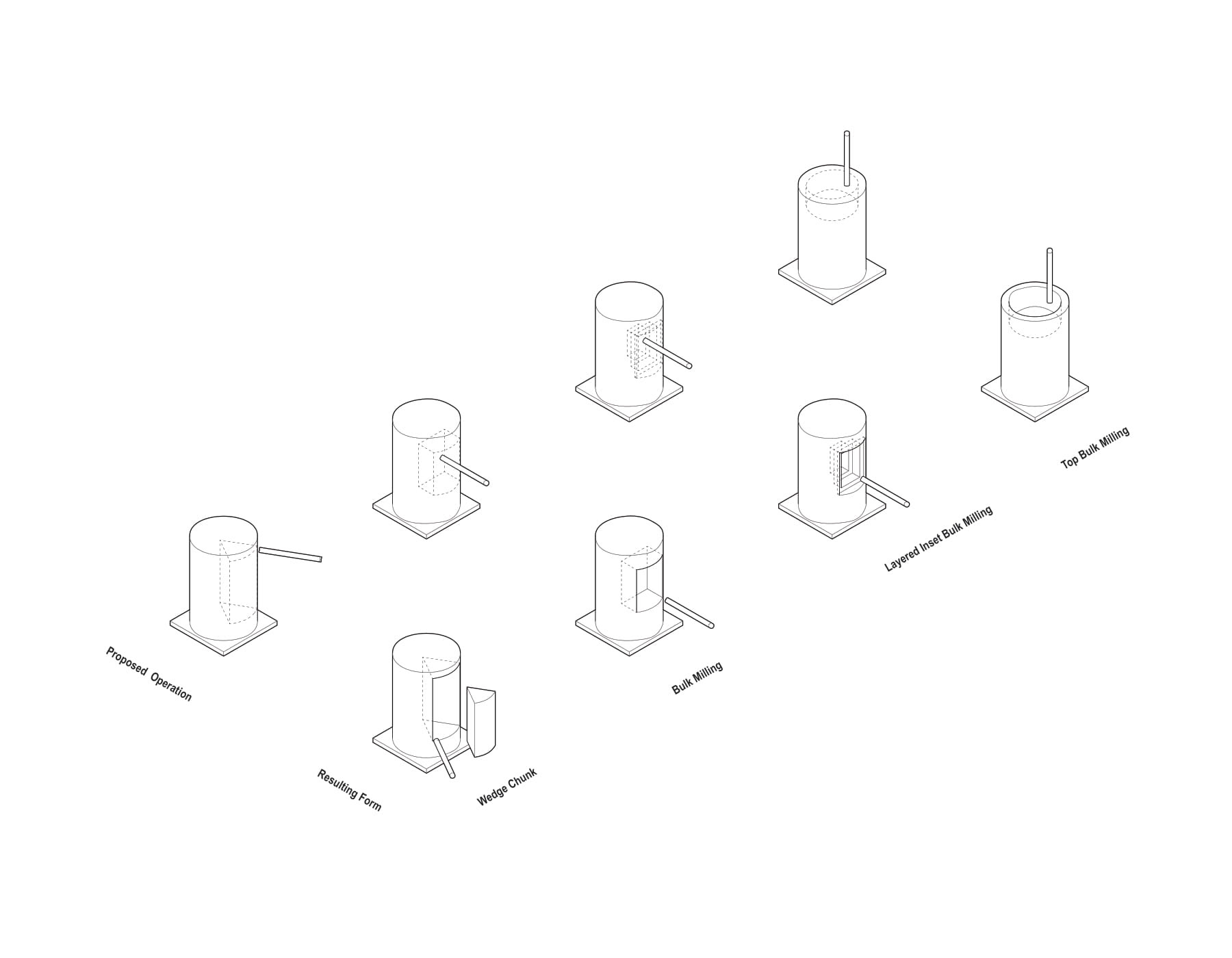
Formal Diagrams