In collaboration with: Harsh Kedia, Christoph Eckrich, and Kirman Hanson
Introduction to Architectural Robotics Course Brief
Introduction to Architectural Robotics is an entry-level course that exposes students to various aspects of industrial robots and automated fabrication including hands-on programming, workflow simulation, sensors, fixtures, and the tactics needed for designing flexible automation. This course will empower the student with the fundamental software and hardware knowledge necessary to do advanced fabrication in subsequent courses. Structured, competency-building exercises within the lab environment will be the method used to develop tacit knowledge of the equipment.
CMU School of Architecture
Course Statement
Over the course of this semester we have learned varying approaches to designing automated workflows. These are culminating in a comprehensive project combining the various methods we have been exposed to throughout the semester. Using online-teaching procedures, RAPID programming, RobotStudio, and HAL we are expected to fabricate a complex mold for casting a concrete structure. The tools implemented are an IRB 6640 and a large stationary hot-wire cutter. It has been a long and challenging process, as we took on an unconventional formal direction. The product and process are outlined below.
Final Drawings & Casts
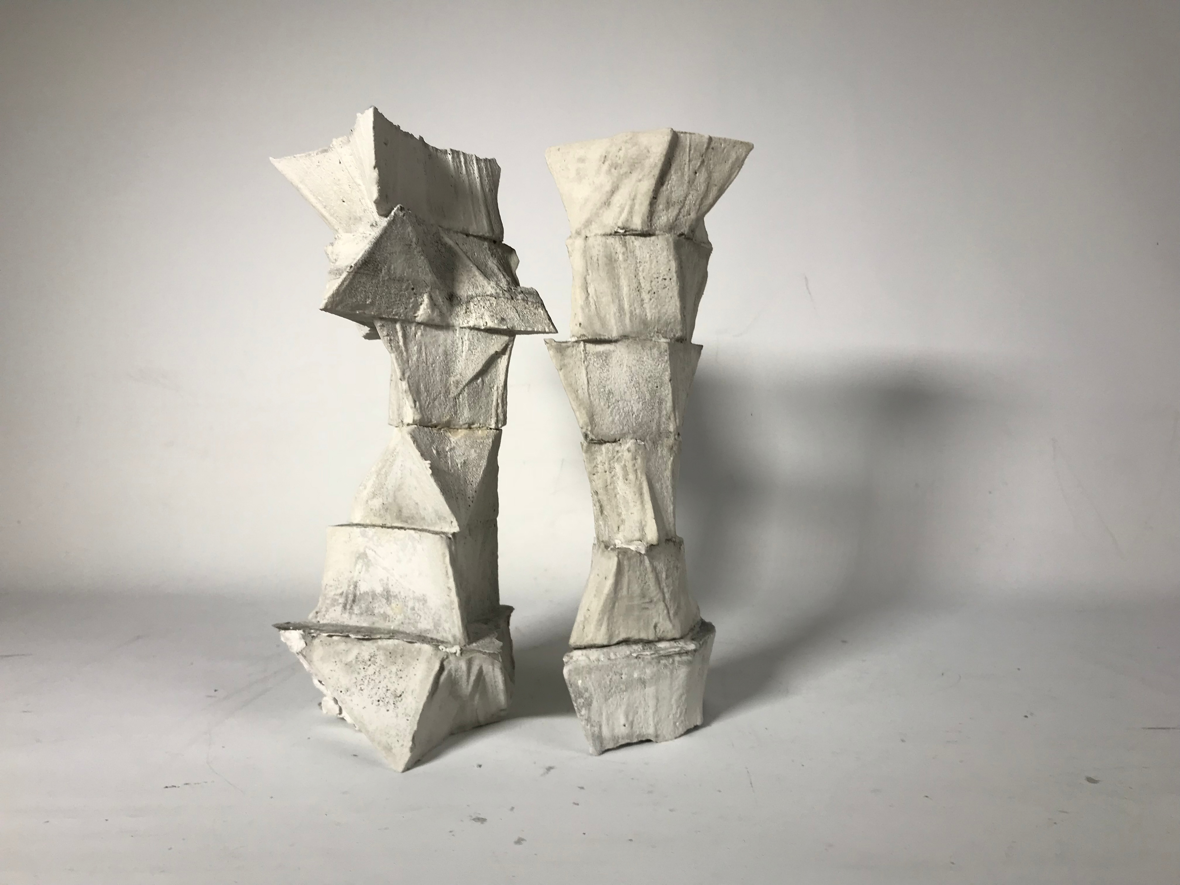

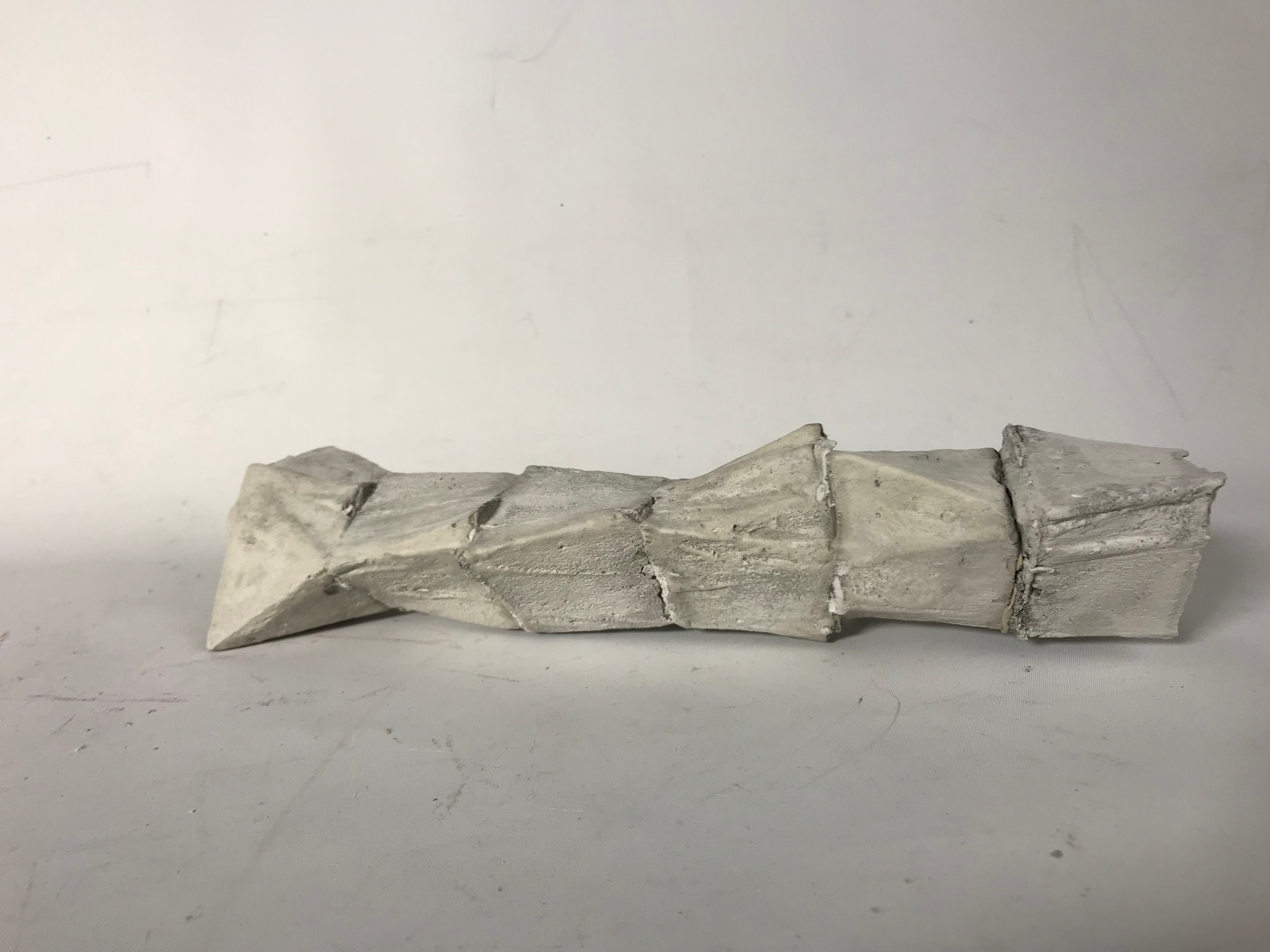

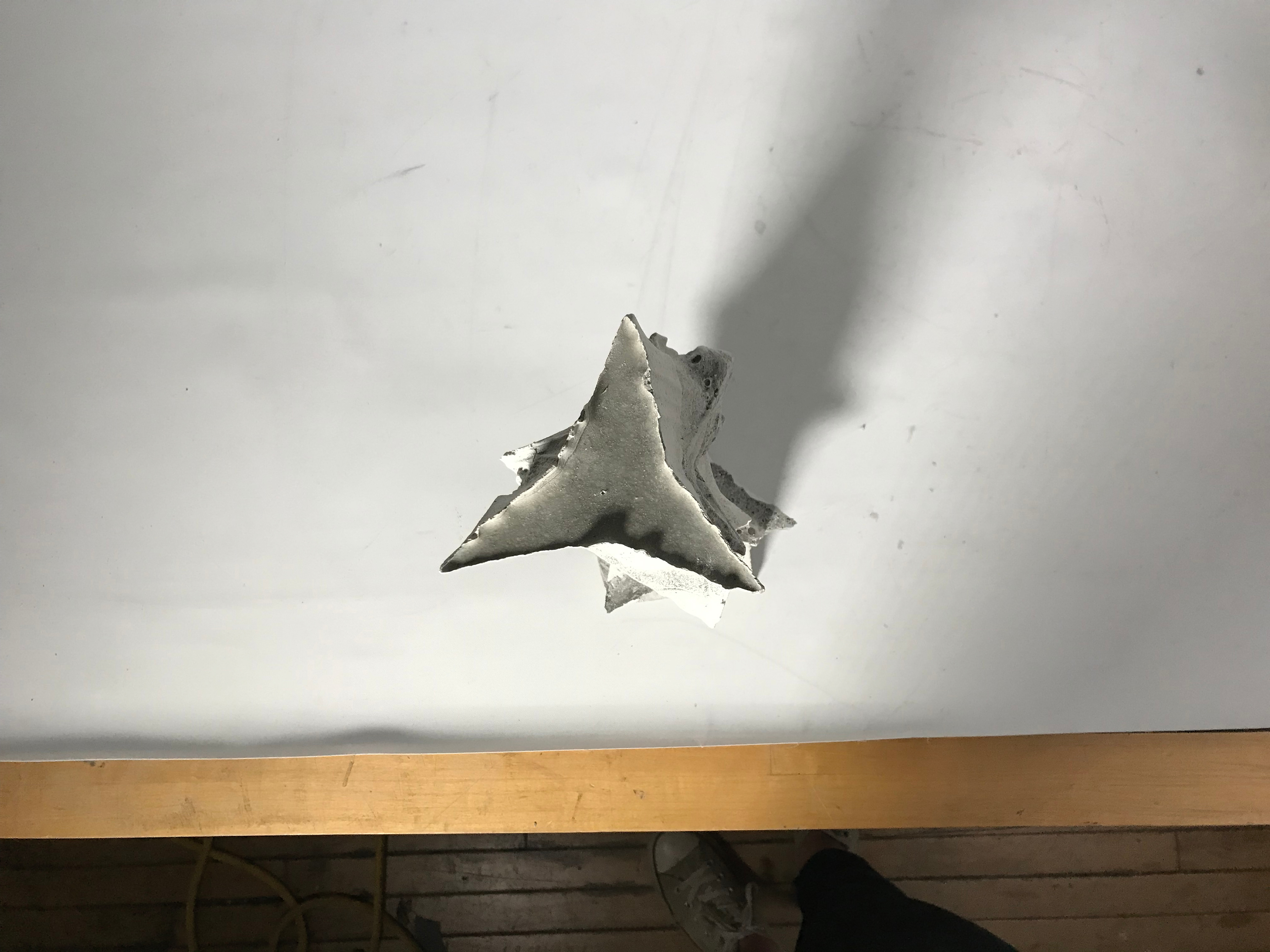
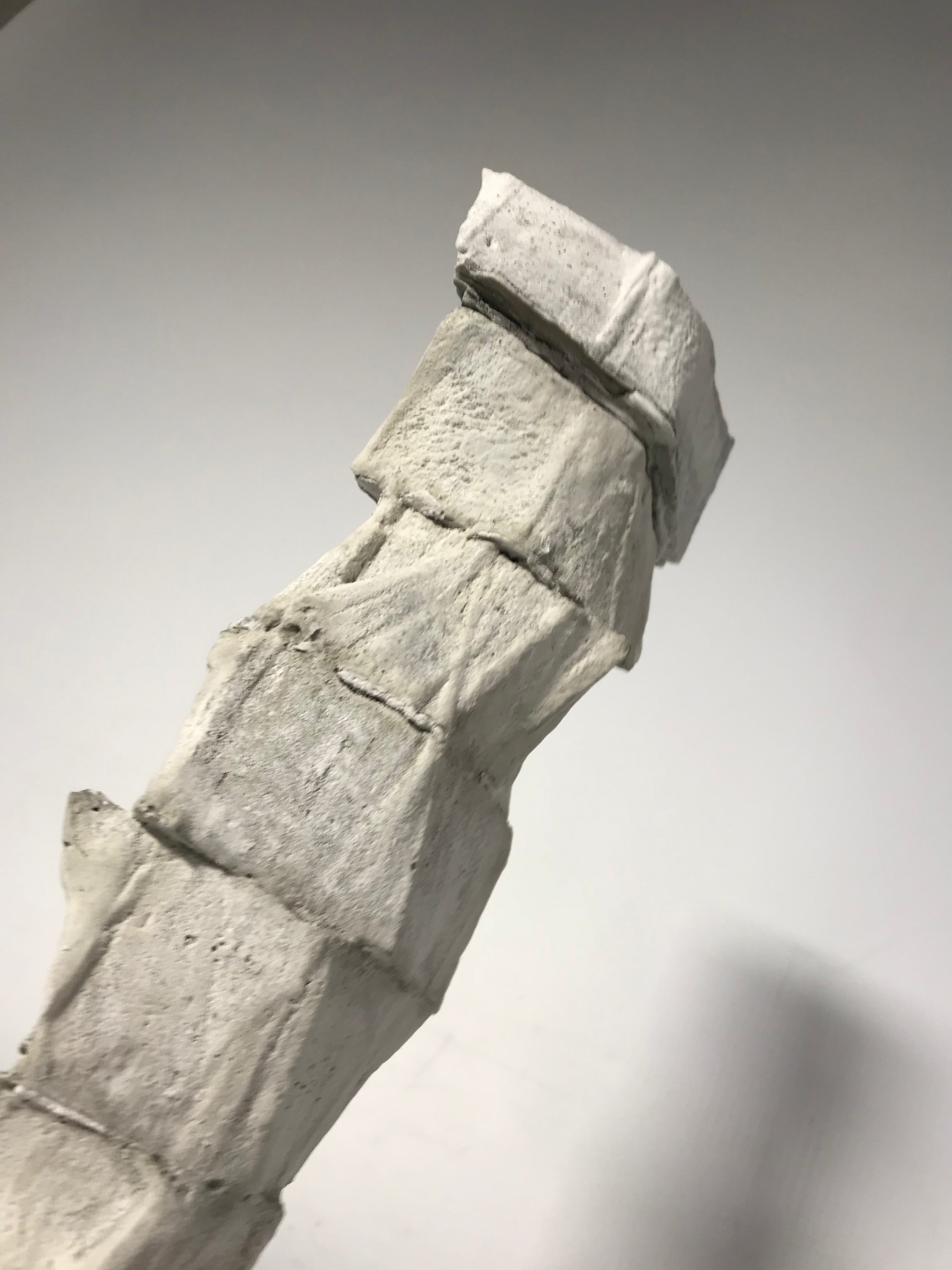
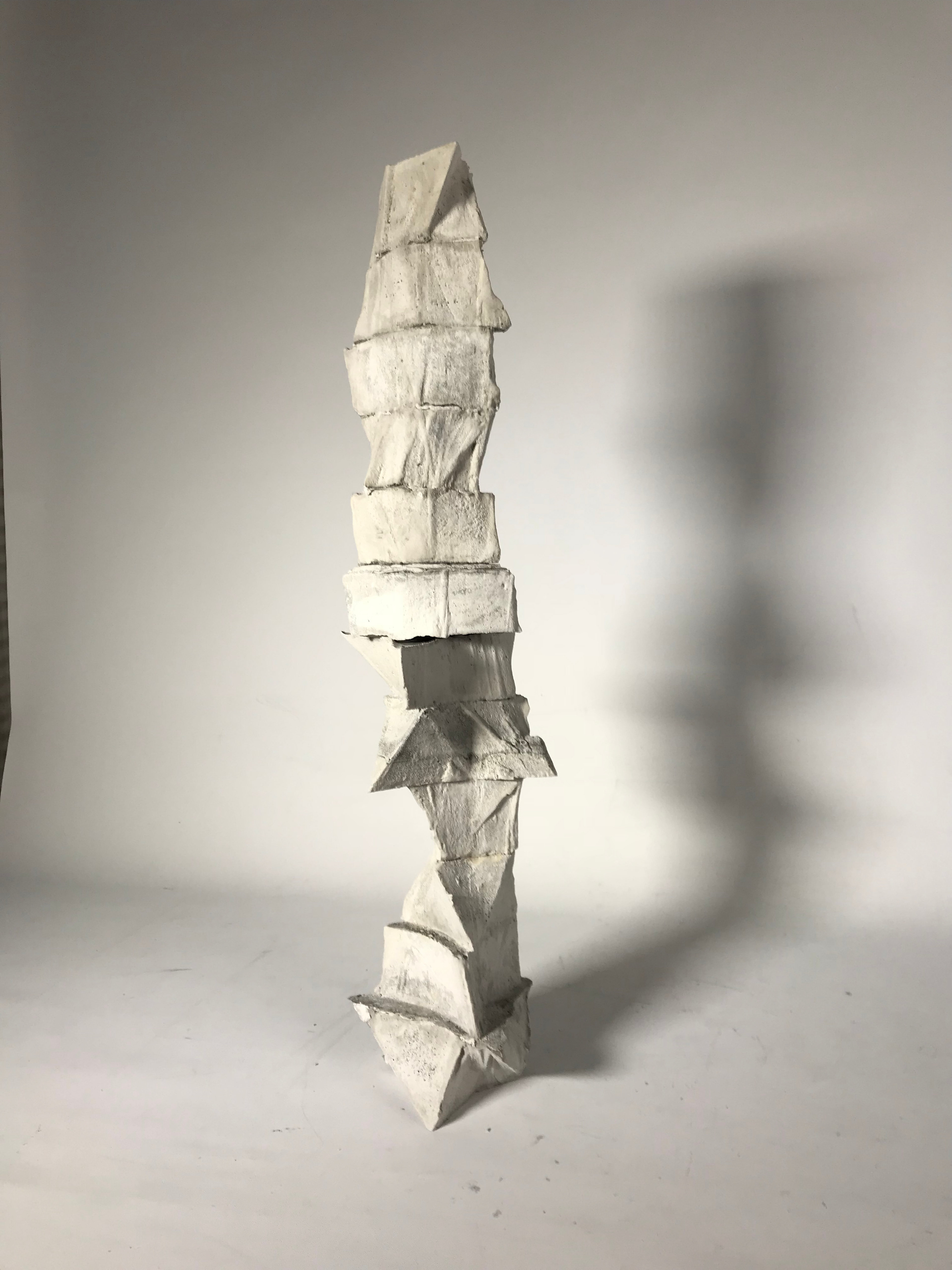
Final Design
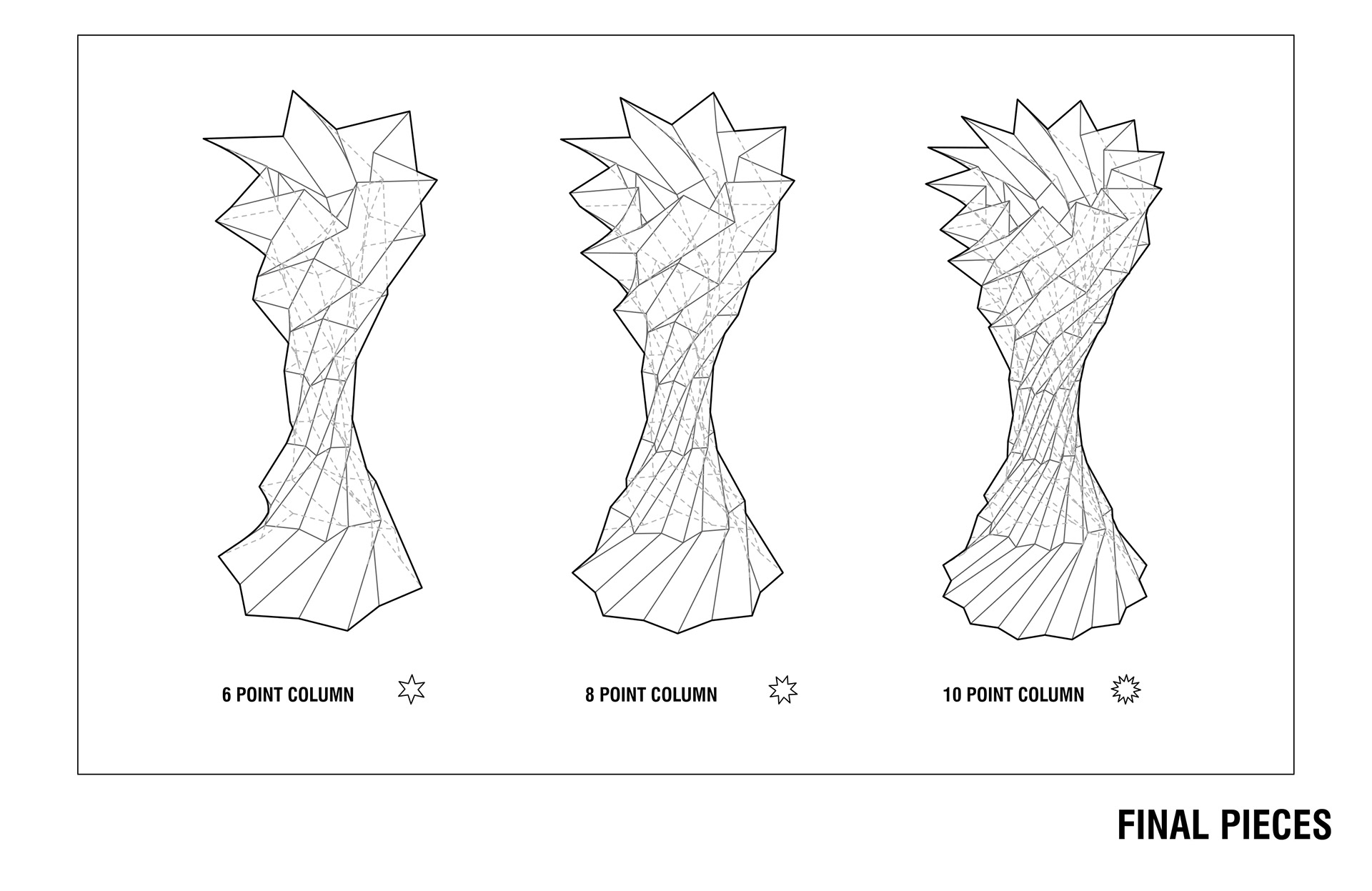
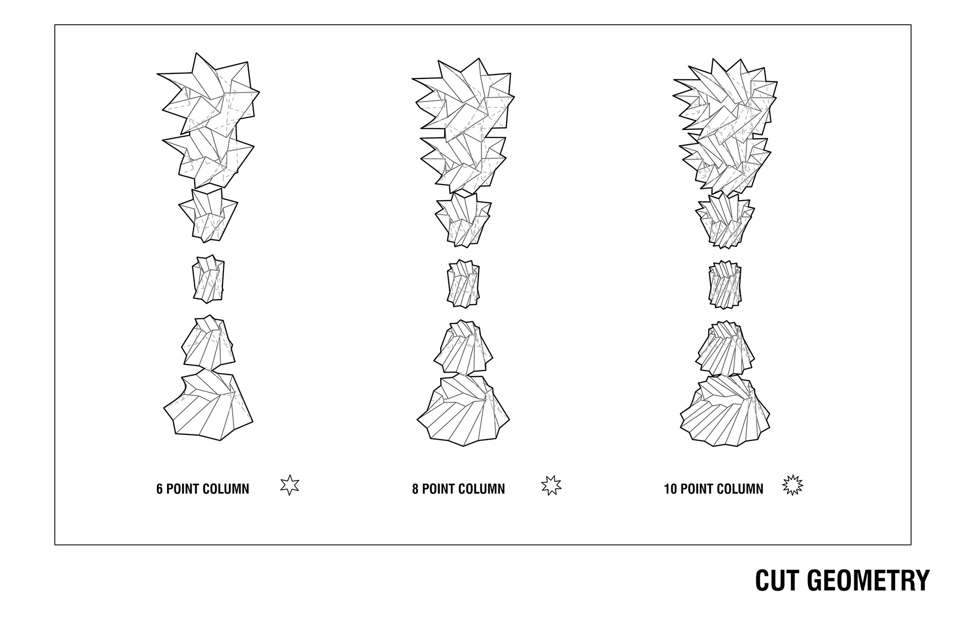
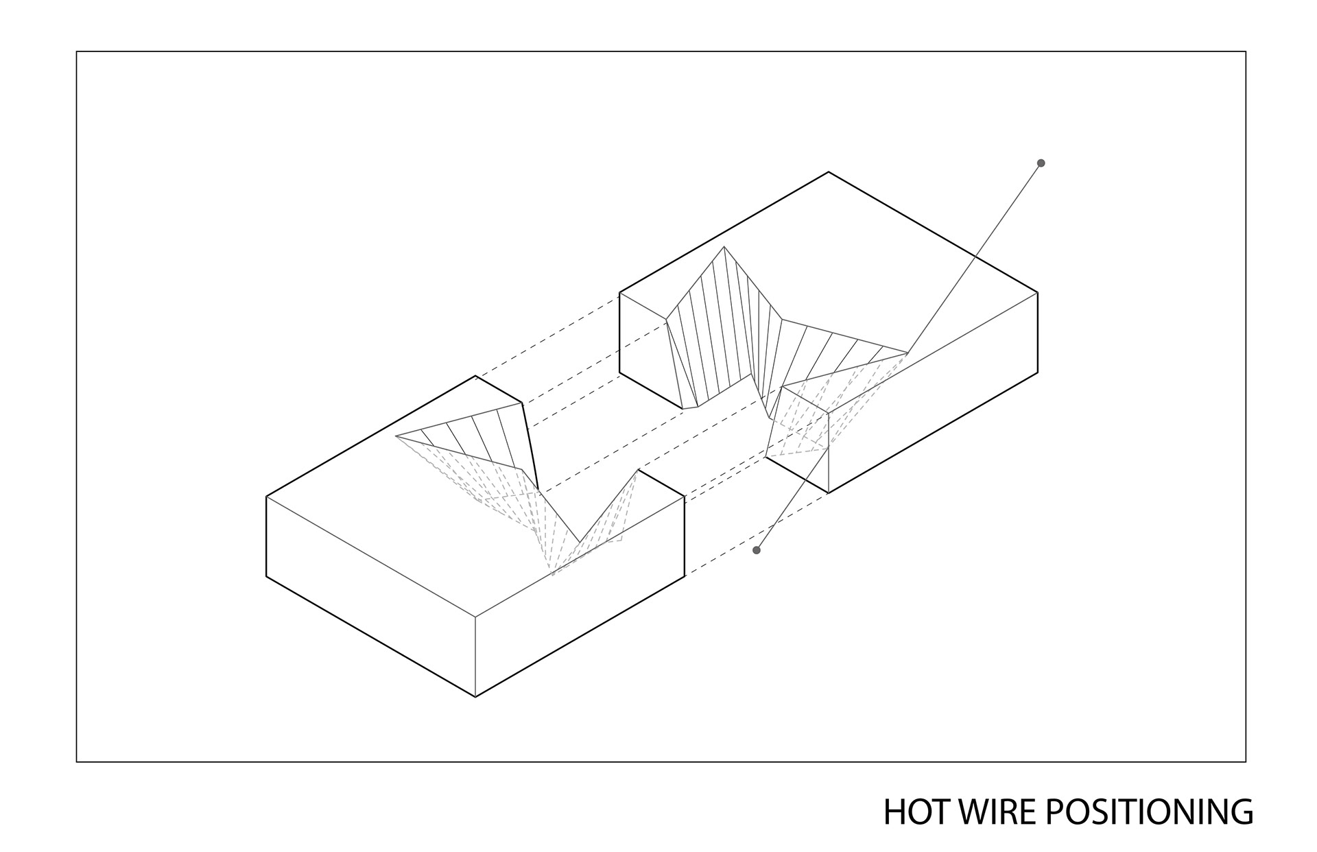
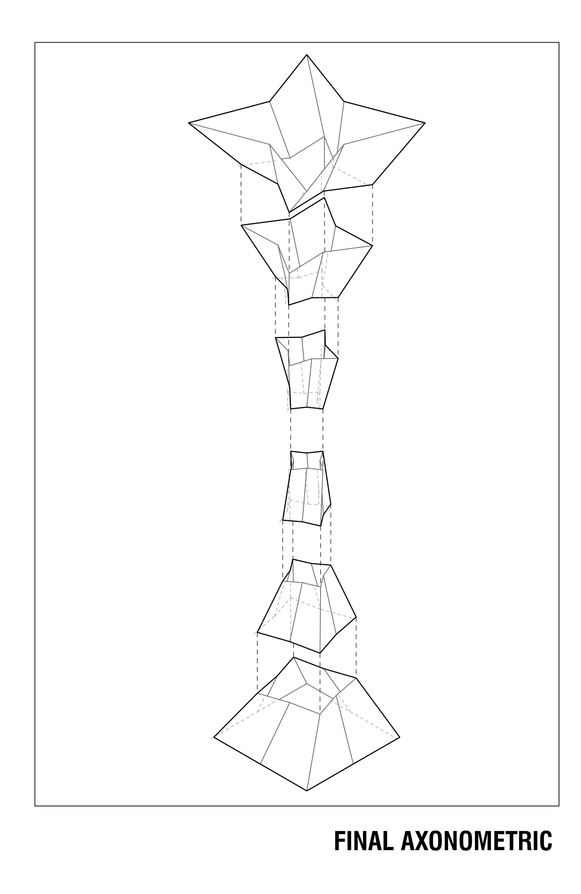
For the final iteration of the project that was to be cut with the industrial robot, we decided to simplify the form and transformation. The primary concerns were that the complexity and number of side of the original forms would require excessive rotation of the robot arm. As such, to avoid coupling errors and feasibility issues in regards to scale and symmetry, we simplified the form to distort from a square to a four pointed star. Even with the simplified geometry, we were unable to cut the entire piece in one cut and had to divide each layer into two halves. This allowed for a smaller domain of rotation for the robot and ultimately allowed the script to be flushed out and function. In addition, the simplification allowed for each level to be symmetrical, thus further simplifying and streamlining the code generation and cutting process. Despite these simplifications, we maintained a similar formal logic to retain a comparable level of elegance, poise, and grace inherent in the initial vision.
Design Intent
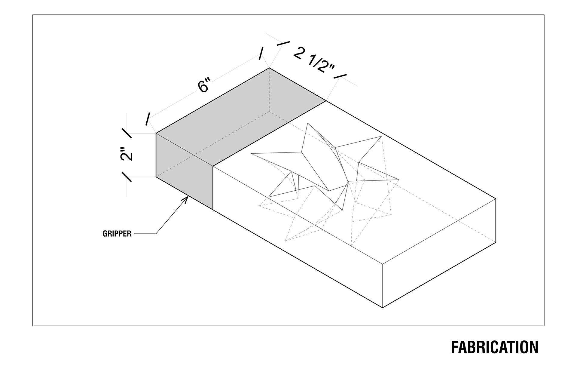
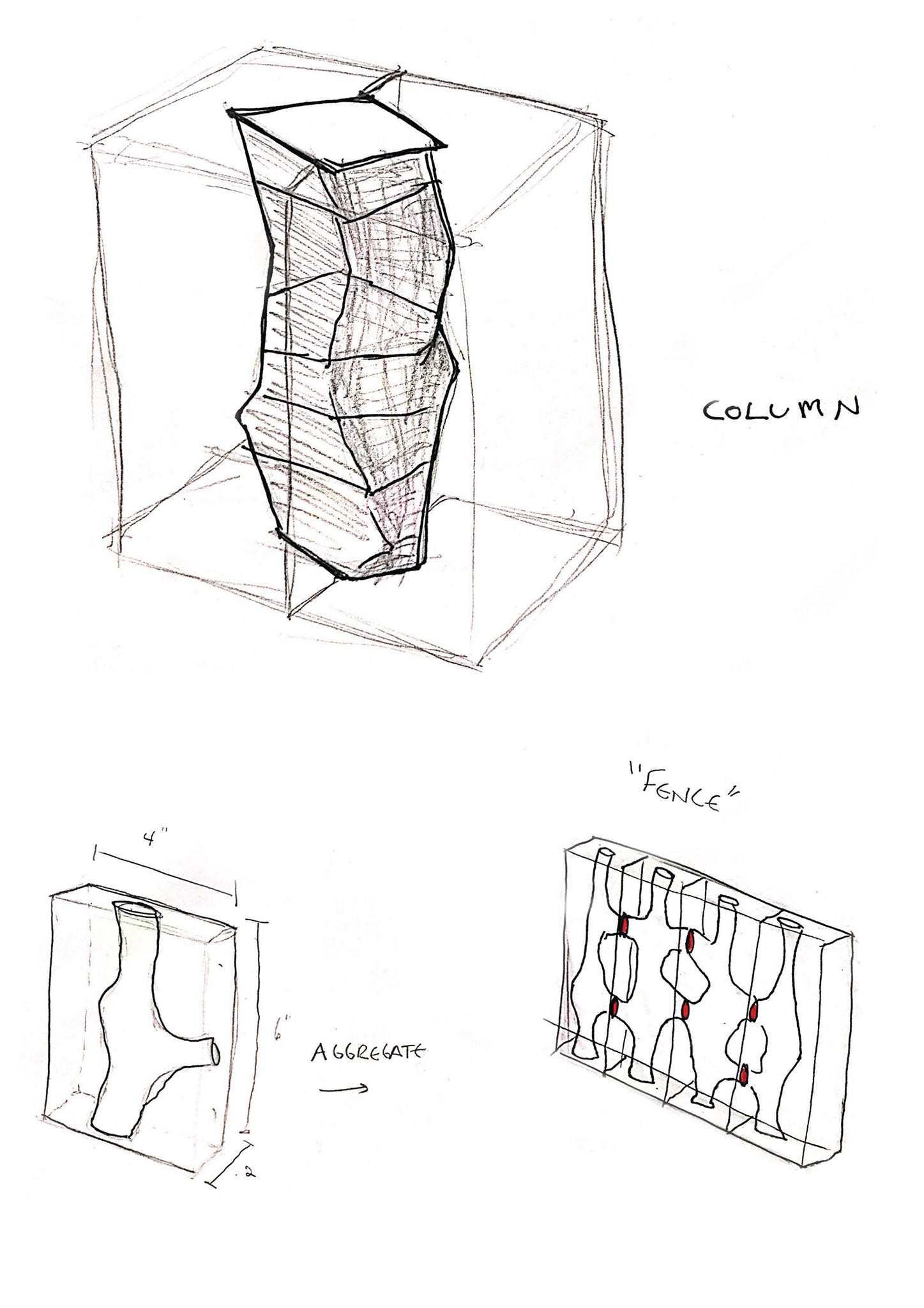
The brief asked to design a panel, and naturally we began to wonder what sort of forms could be possible outside of a 2.5D representation. After exploring various precedents, we decided on the typology of a column. Although at first we looked into creating a grid or fence, it ultimately proved to be too intricate for our expertise at the time. Our project took form alongside the idea of using the hot wire cutter as more of a jigsaw than as a normal planar cutting surface. By threading the hot wire through a block of foam and manipulating it with the robotic arm one could create intriguing ruled forms on the interior of the block. These interior forms could then be connected together to form a series of linked negative spaces to be cast and made into replicable solid objects. By using the hot wire cutter in this way, this process allows for the creation of forms that include undercut and twisting forms which would be much less efficient to fabricate with a CNC router.

Initial Design Iterations
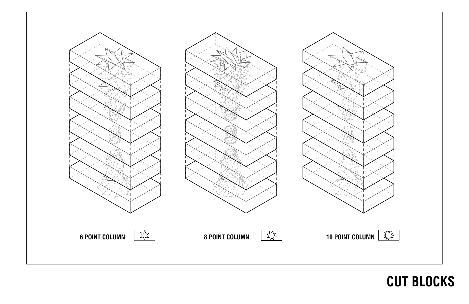
Originally we intended to make a fence-like structure by carving out interior spaces in the foam in both the x and y directions and then linking the pieces of foam together to make a networked mold. Given the time constraint of the project, we modified this idea to a single “module” of the fence, i.e. a column structure. Looking at our initial ideas for the column, we began with the idea of a manipulated extruded polygon, with variations in width as the column moves from top to bottom. From these initial forms we chose the more angular column for both interest in its shape and its more planar sides which would be easier to cut. Ultimately, We also simplified this form from the 8-sided polygon shape of the faces to a four sided column which changes from a square to a star shape as it tapers in the middle.
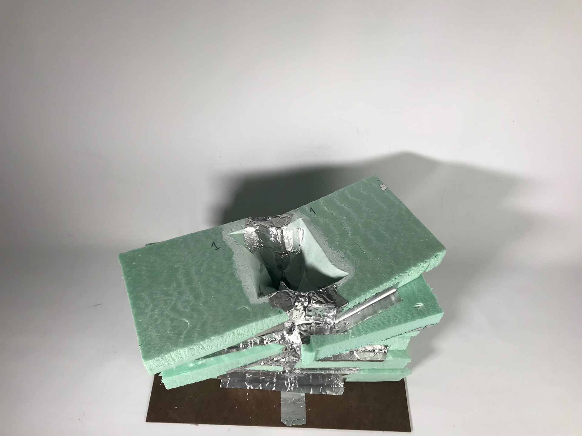
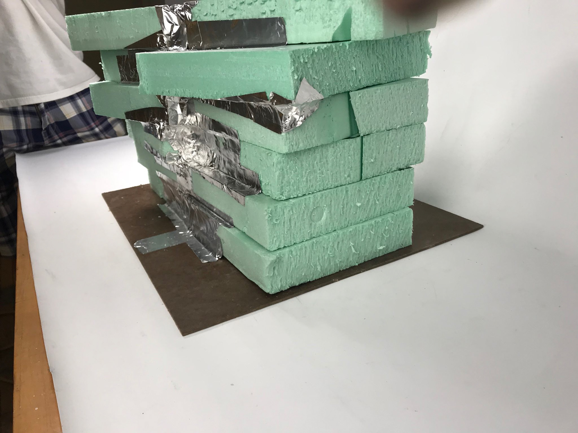
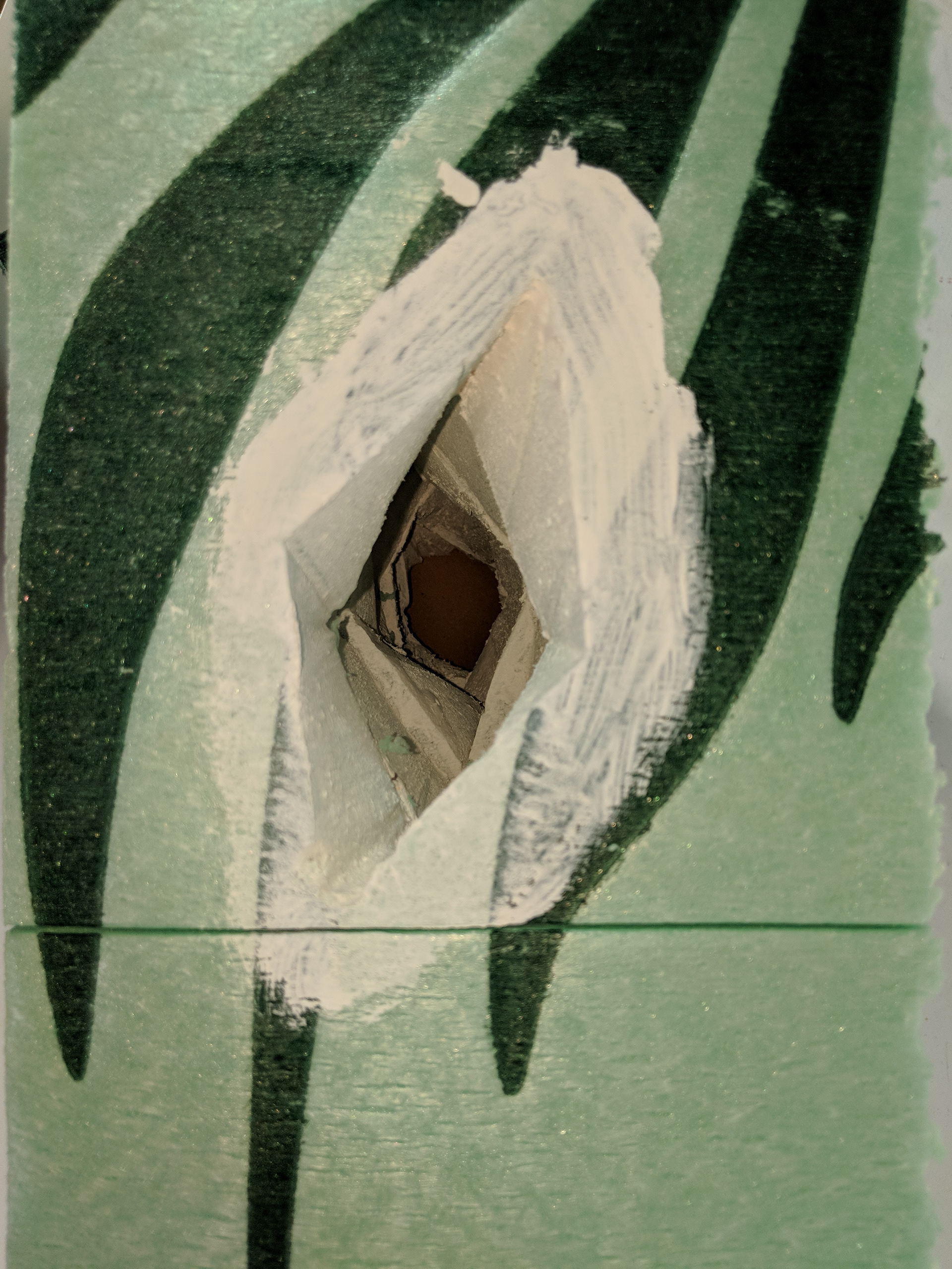
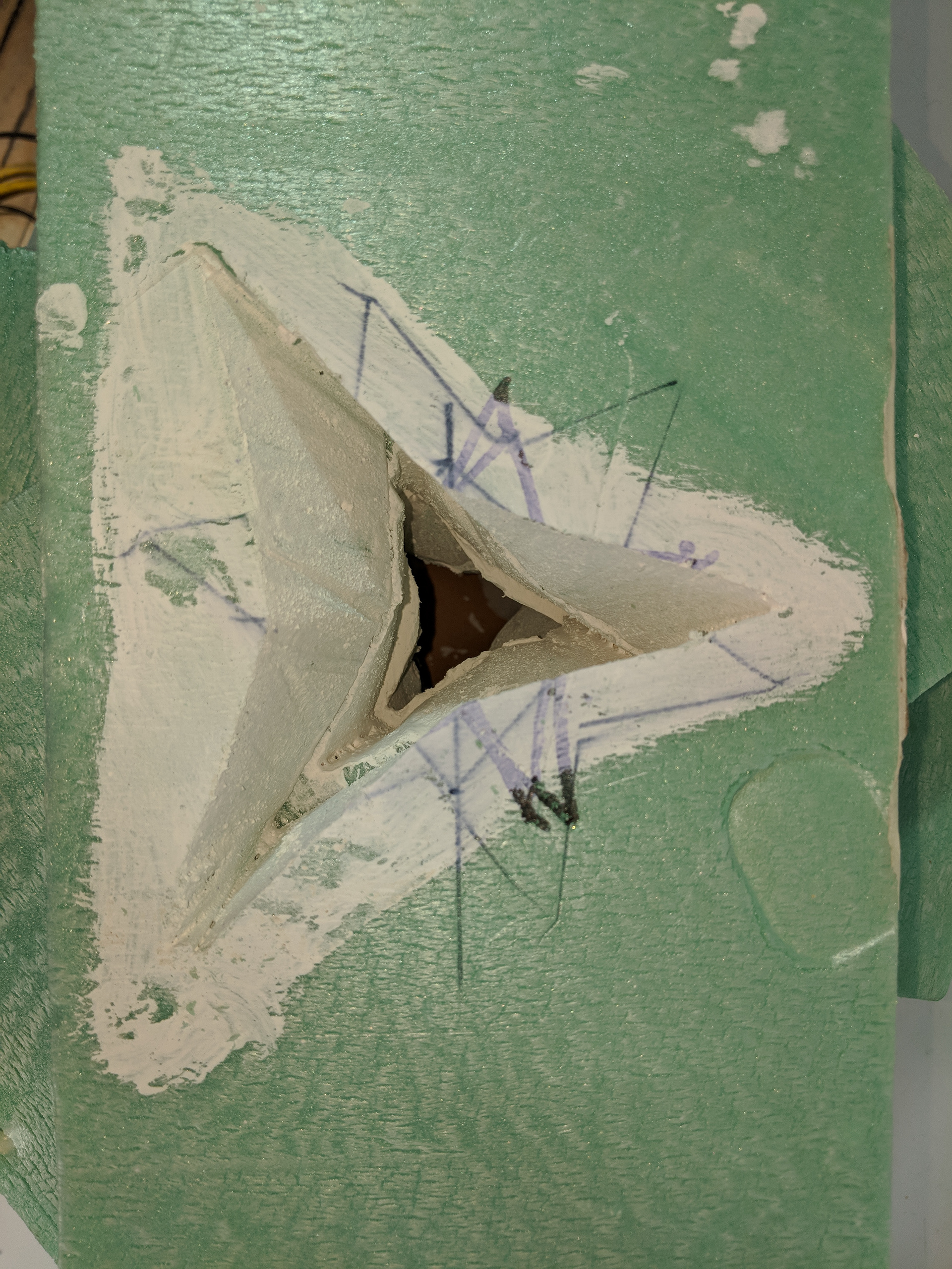
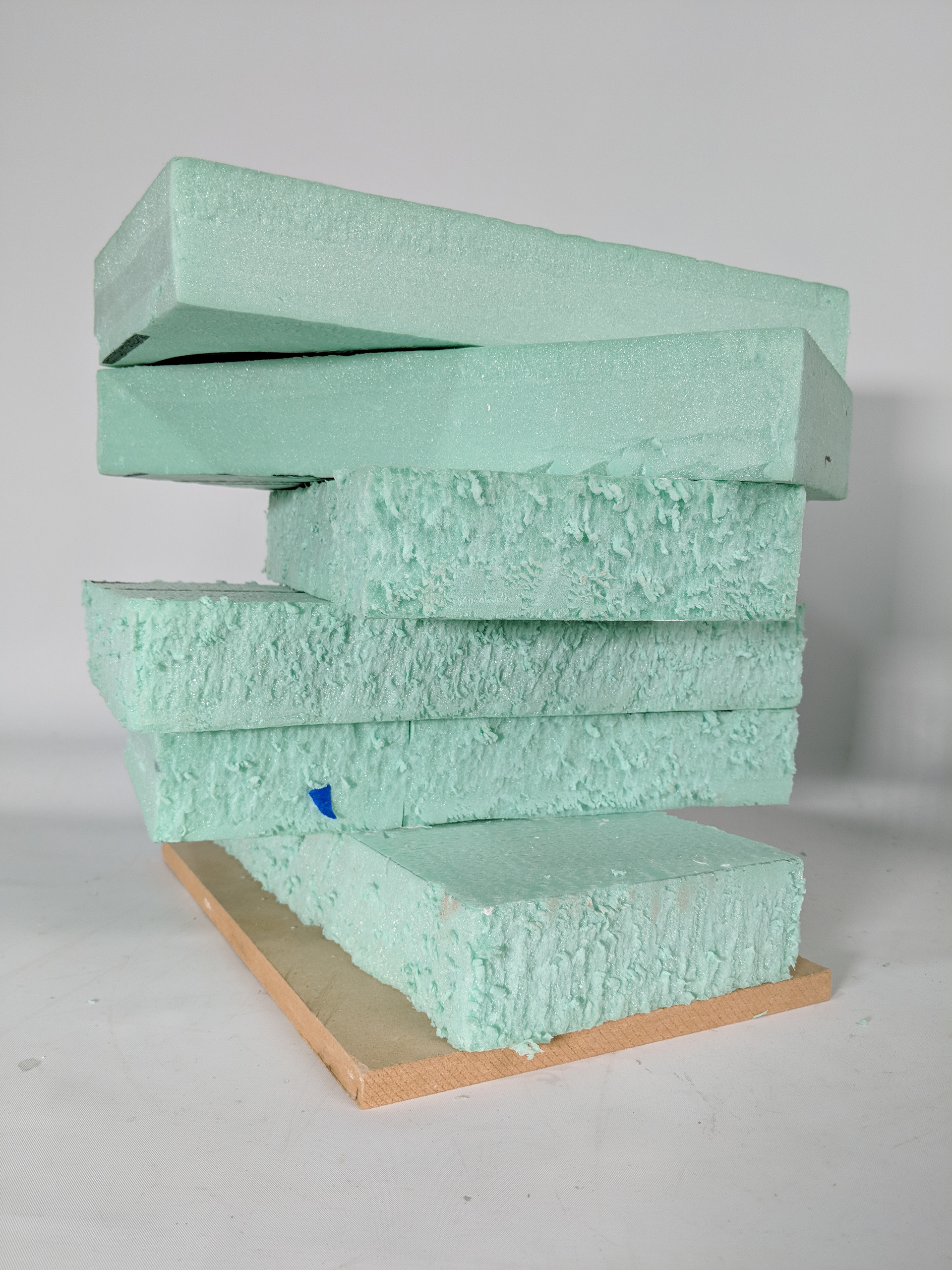
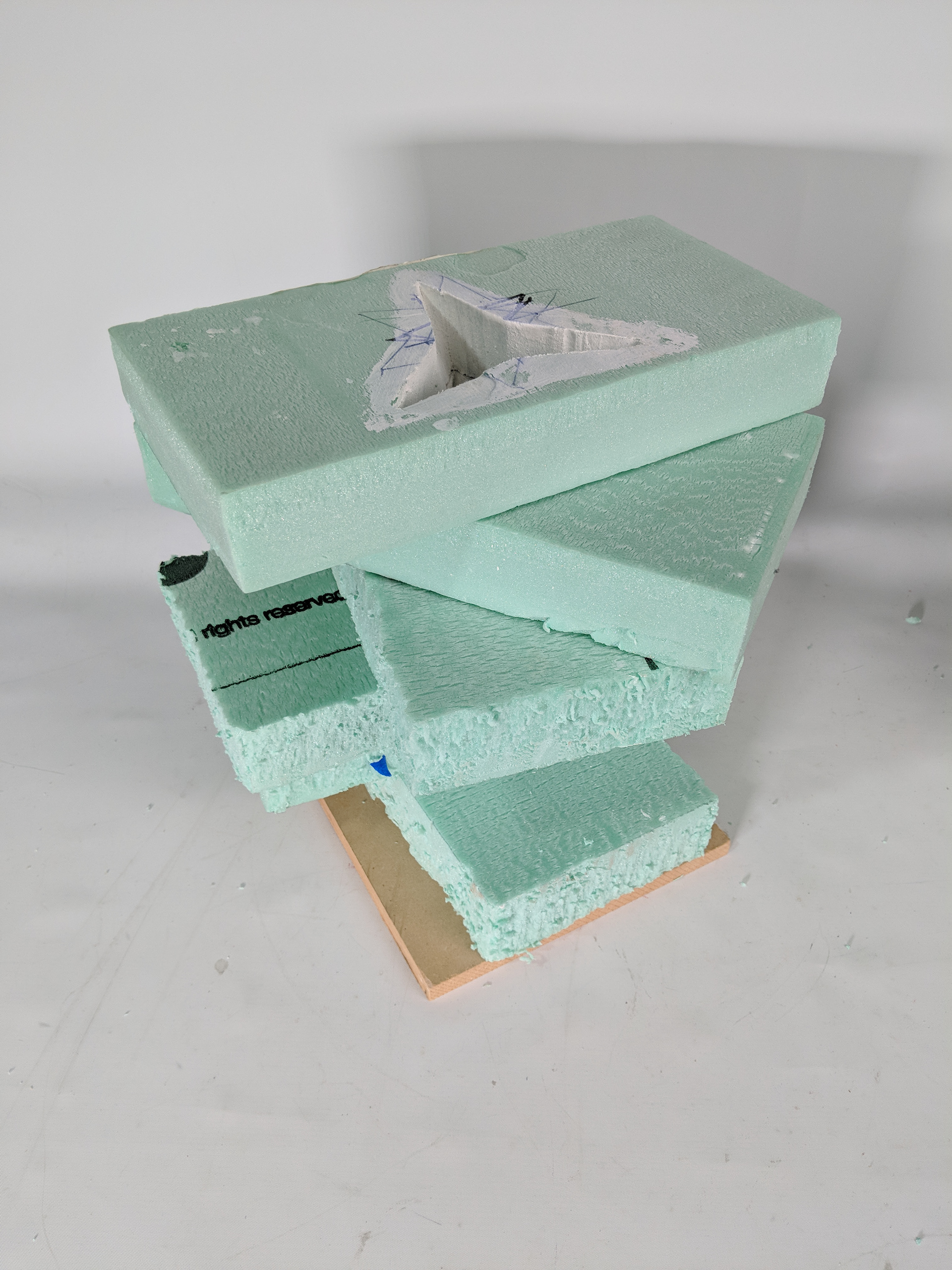
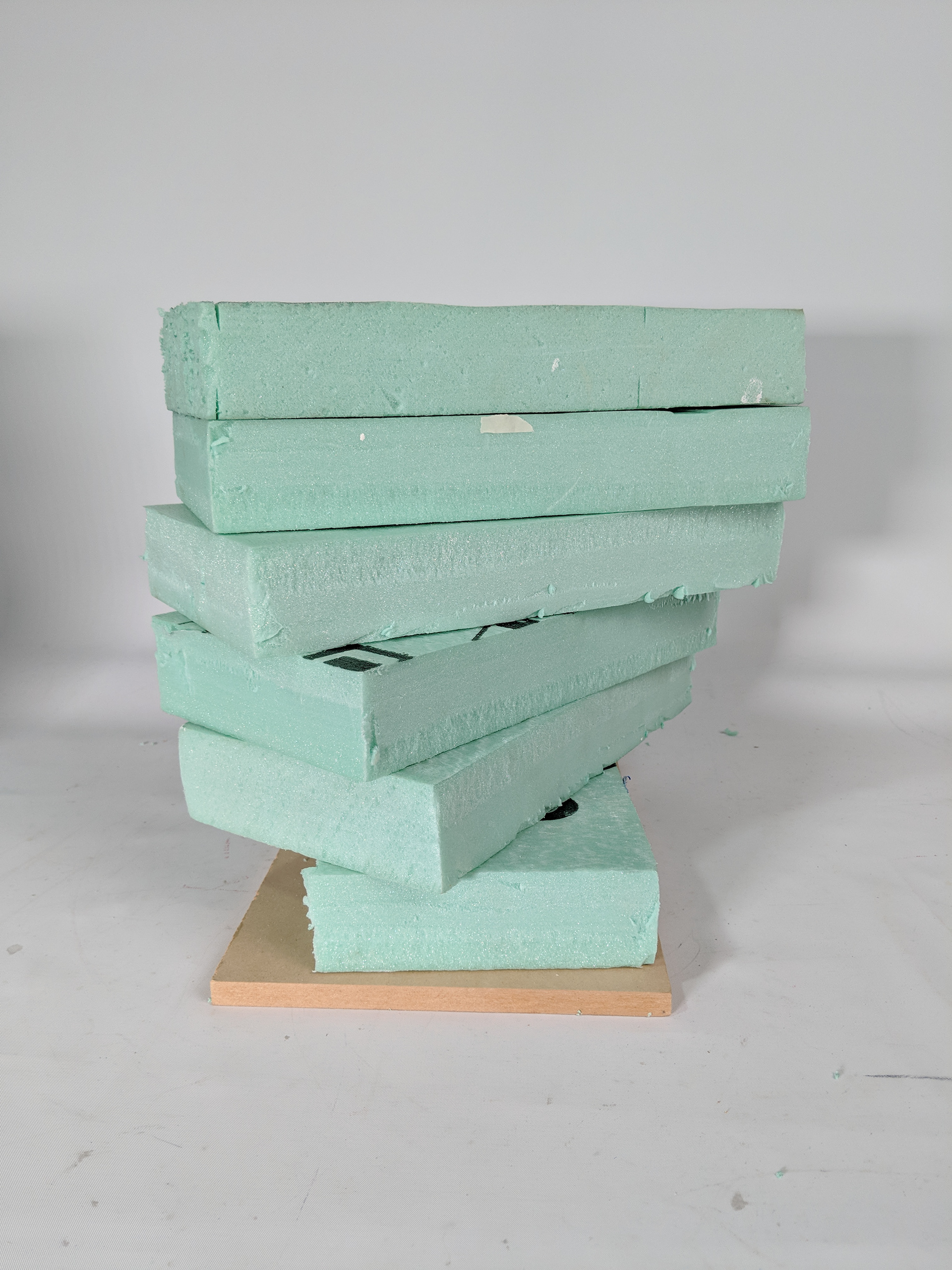
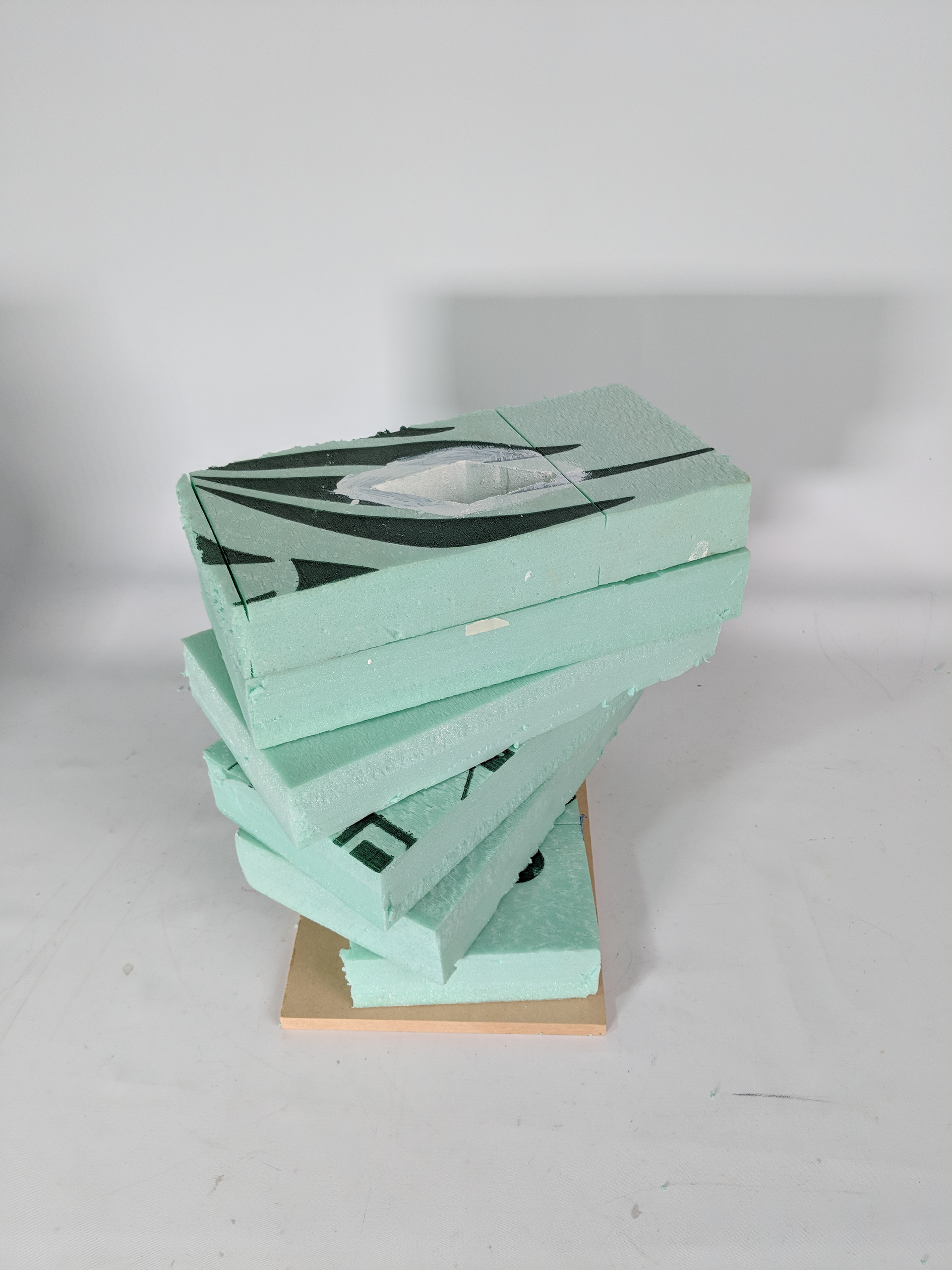
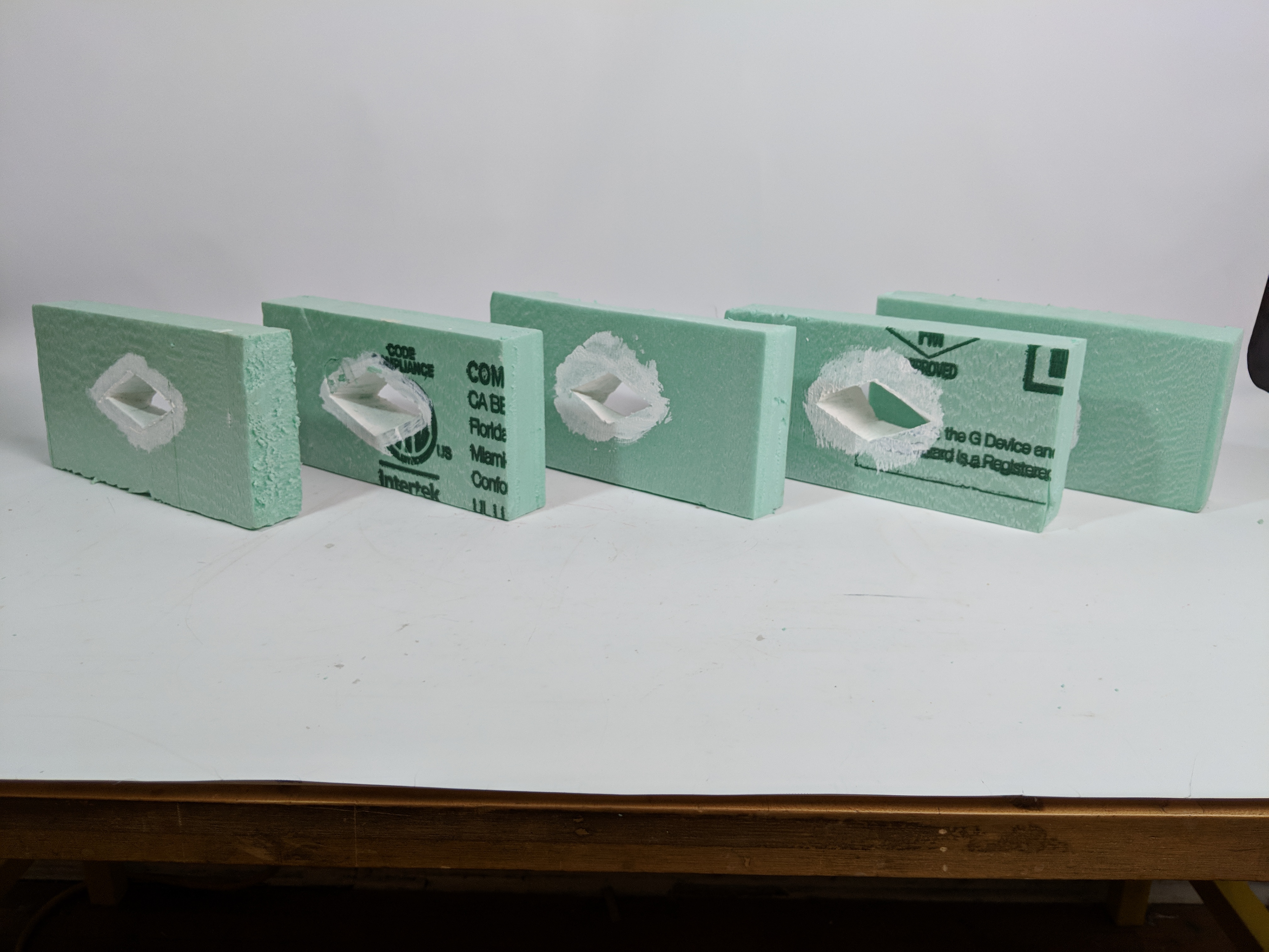
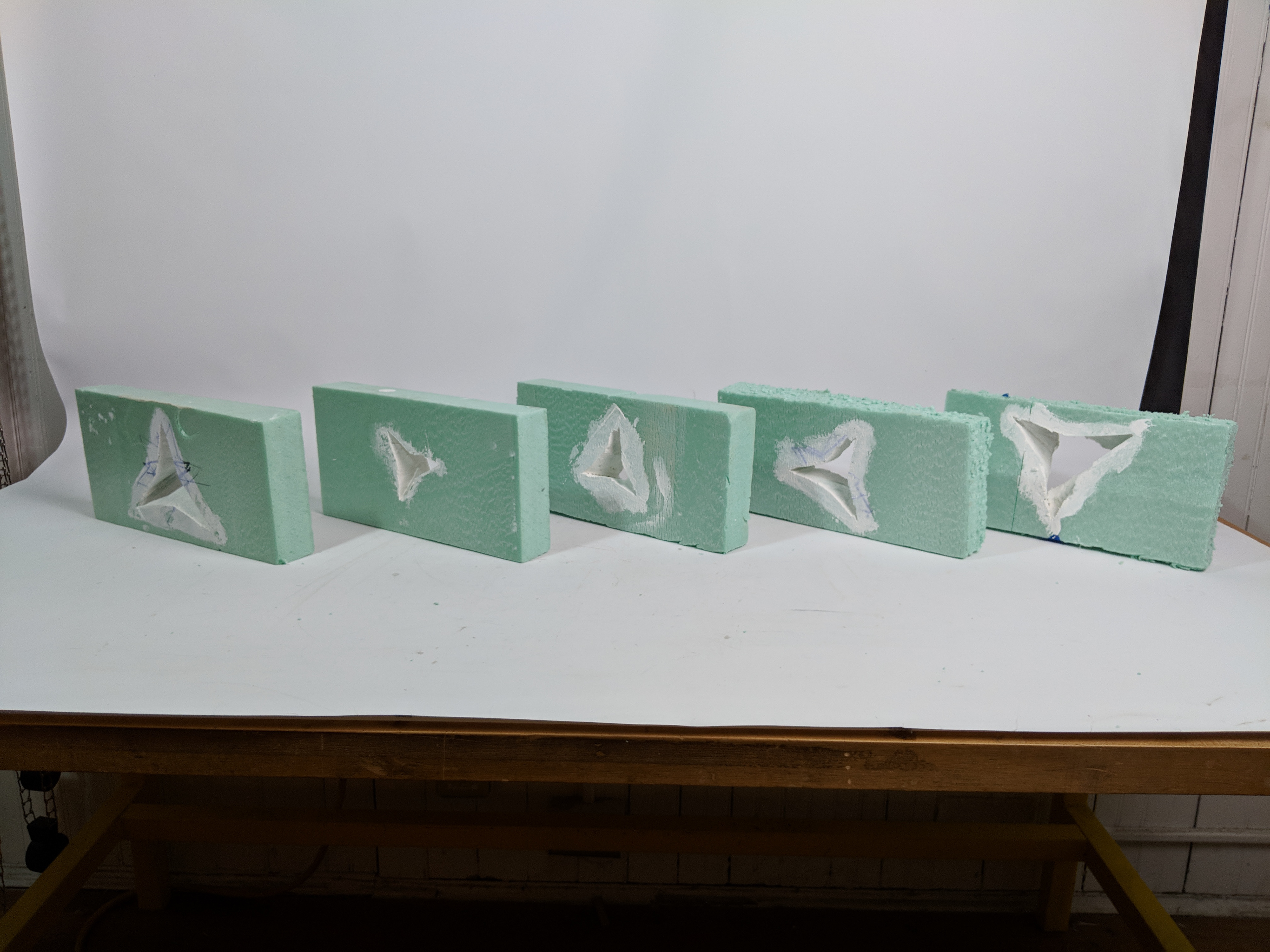
Analog Formwork Explorations
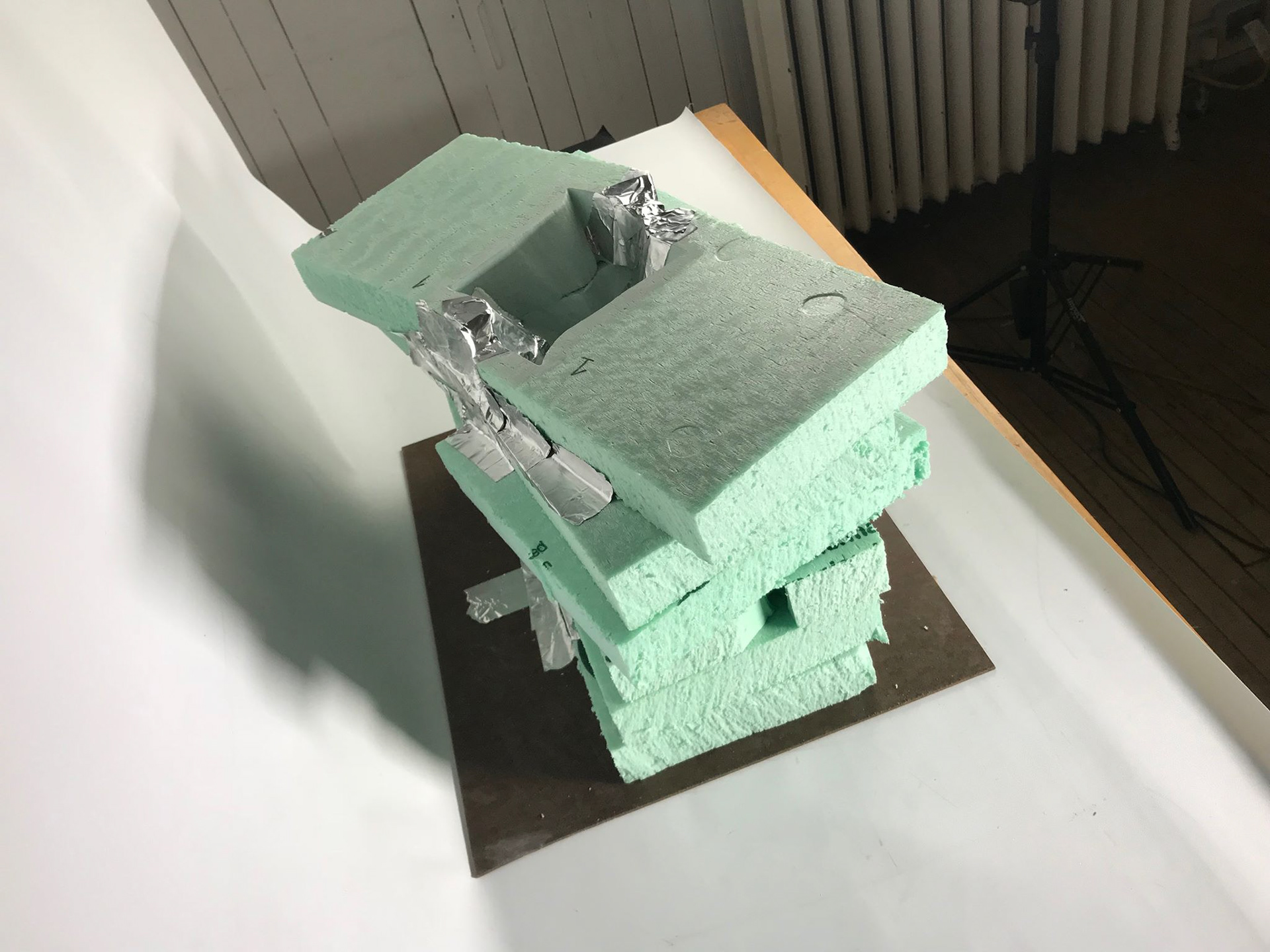
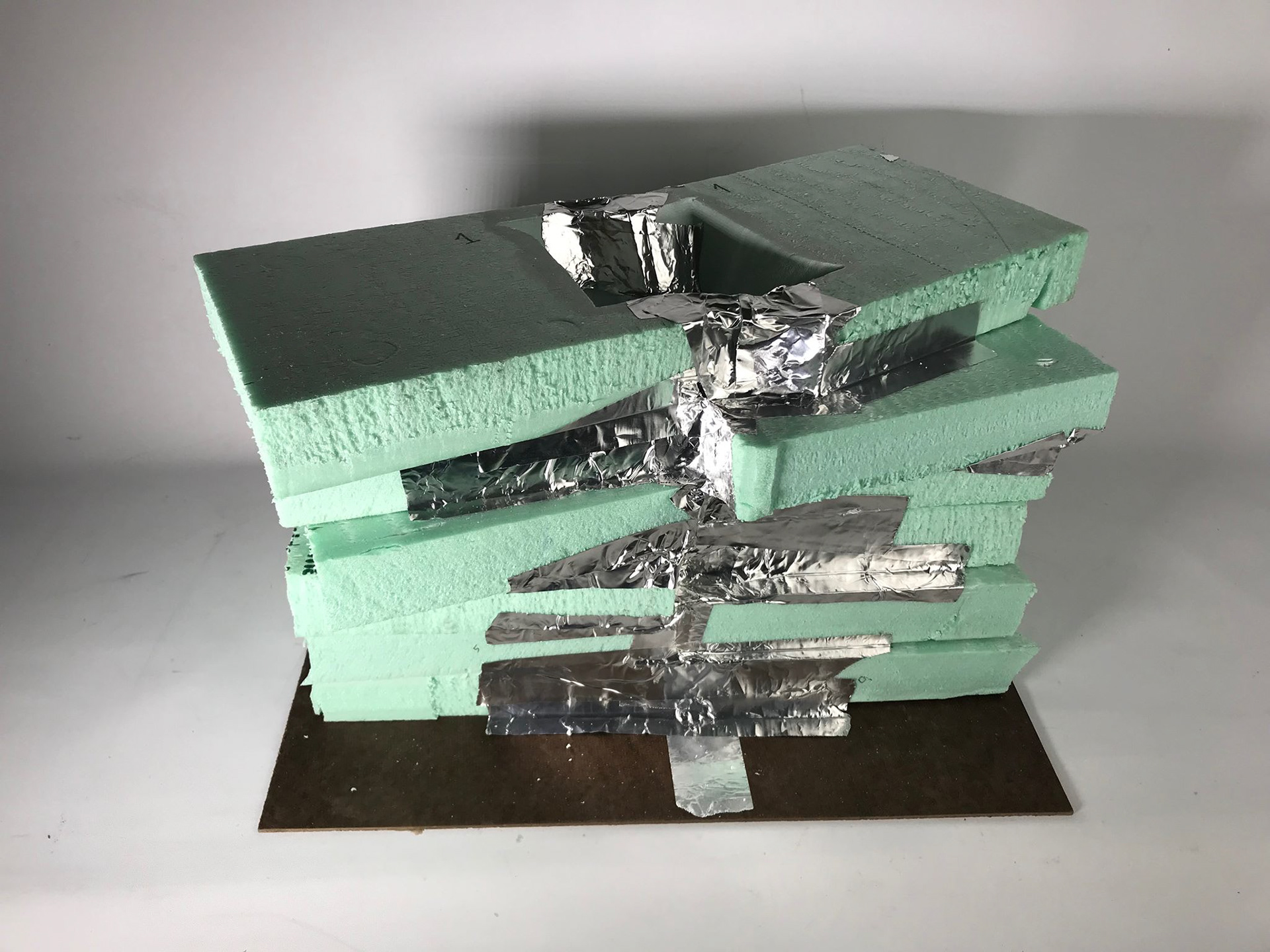
We began by exploring simplified versions of our initial designs. The reduction in the number of points on the polygons used to generate the ruled surfaces allowed us more flexibility to cut them out by hand. Shown on this page and the next are initial iterations of a 2 point and 3 point formwork. We faced quite a few challenges along the way, stemming from human error and material issues. The foam was difficult to cut evenly, and lingering in one spot caused significant burning. We fabricated guides for each face, and attempted to use them to map the ruled surface in-between. This technique had limited success, although it improved further after reducing the heat of the hotwire by about a third.
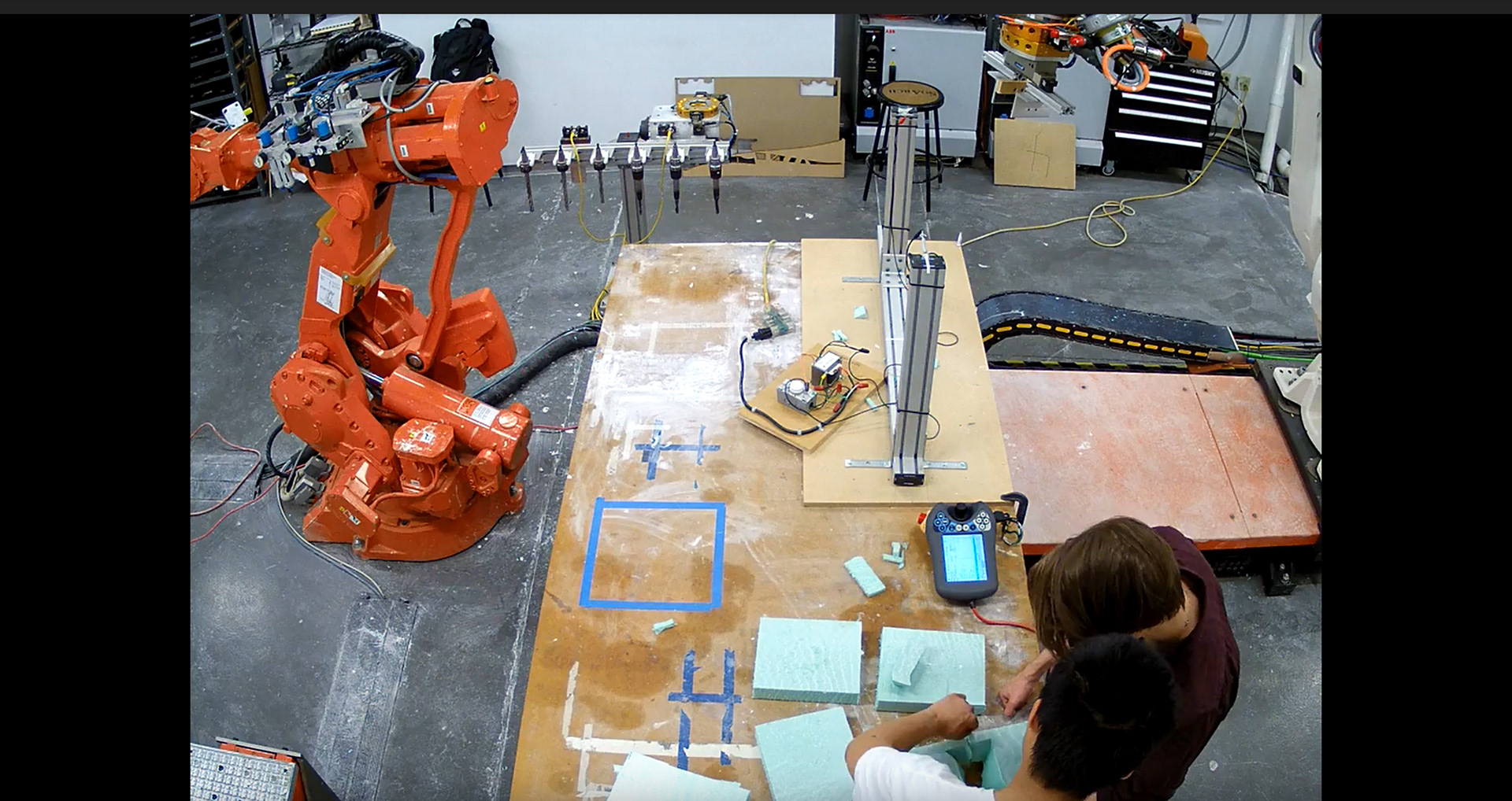
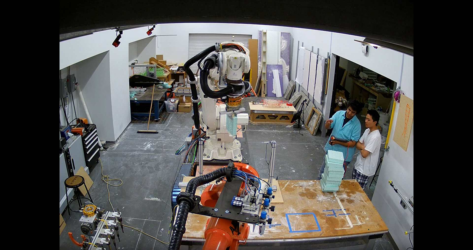
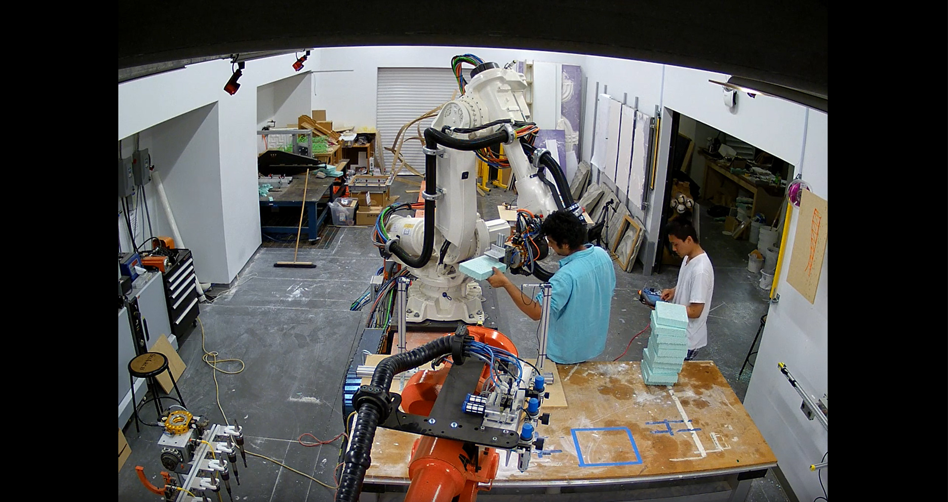
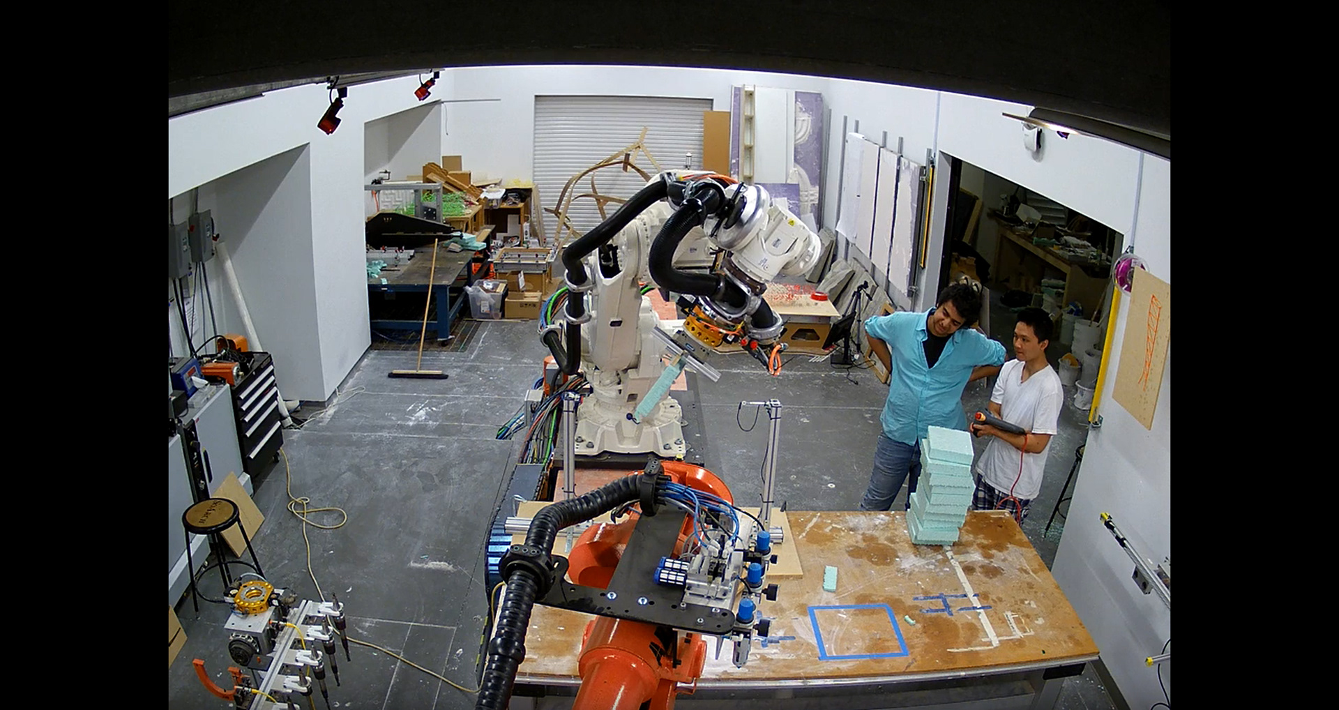
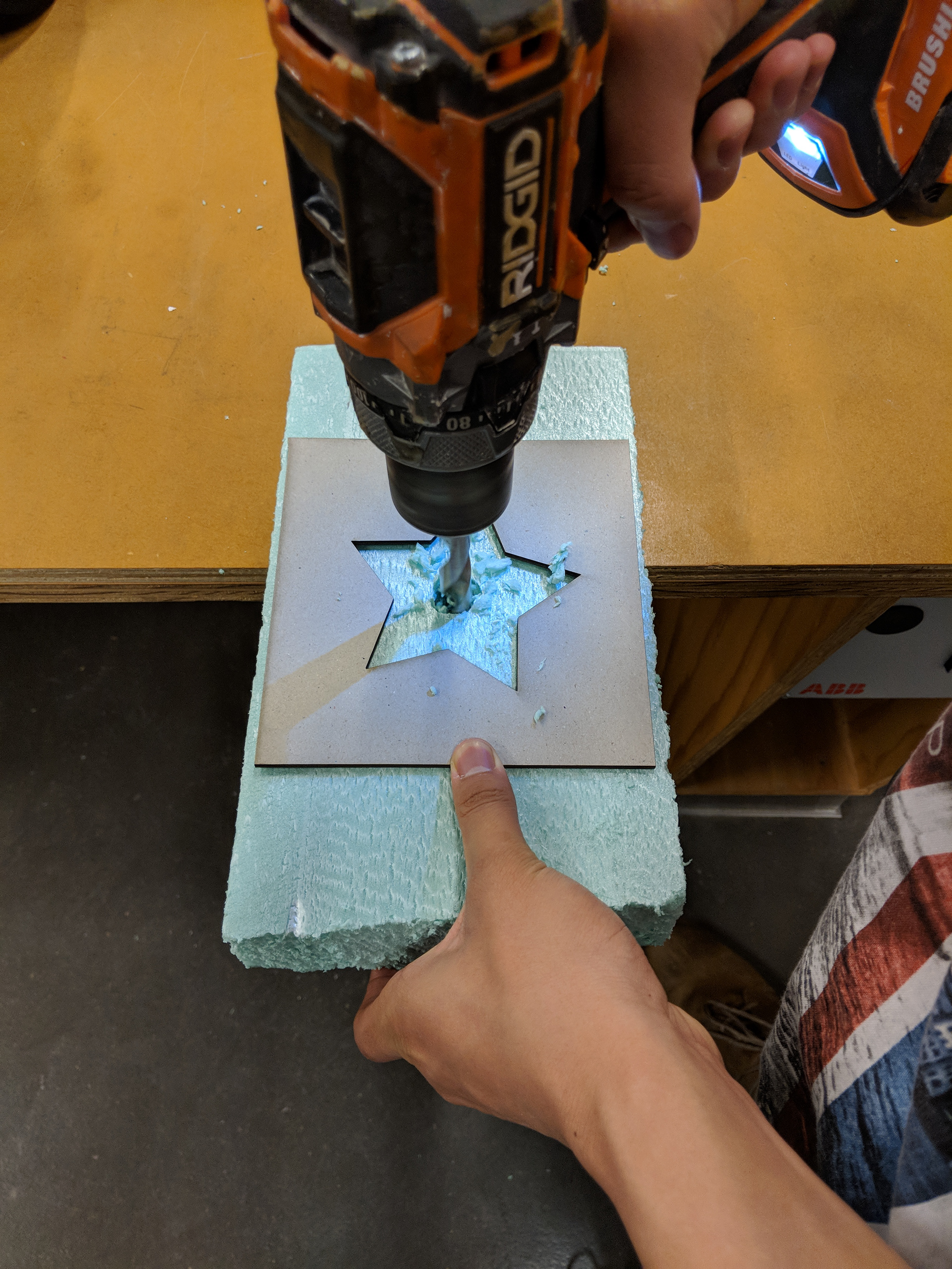
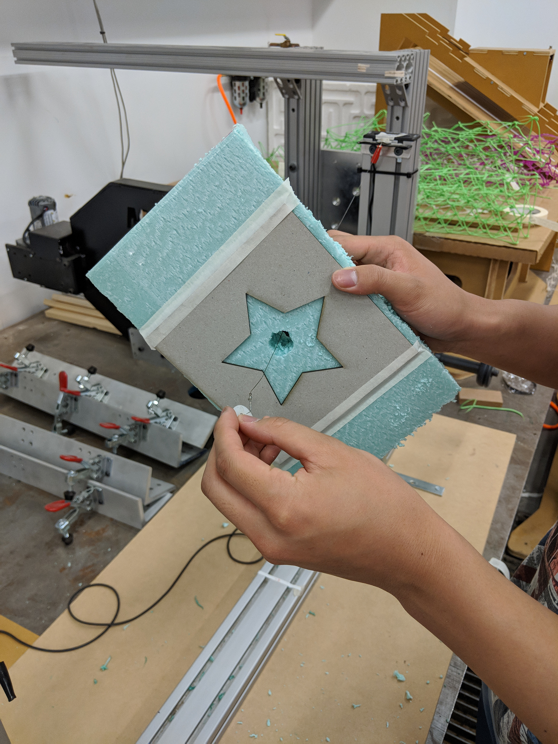
Procedure Explanation
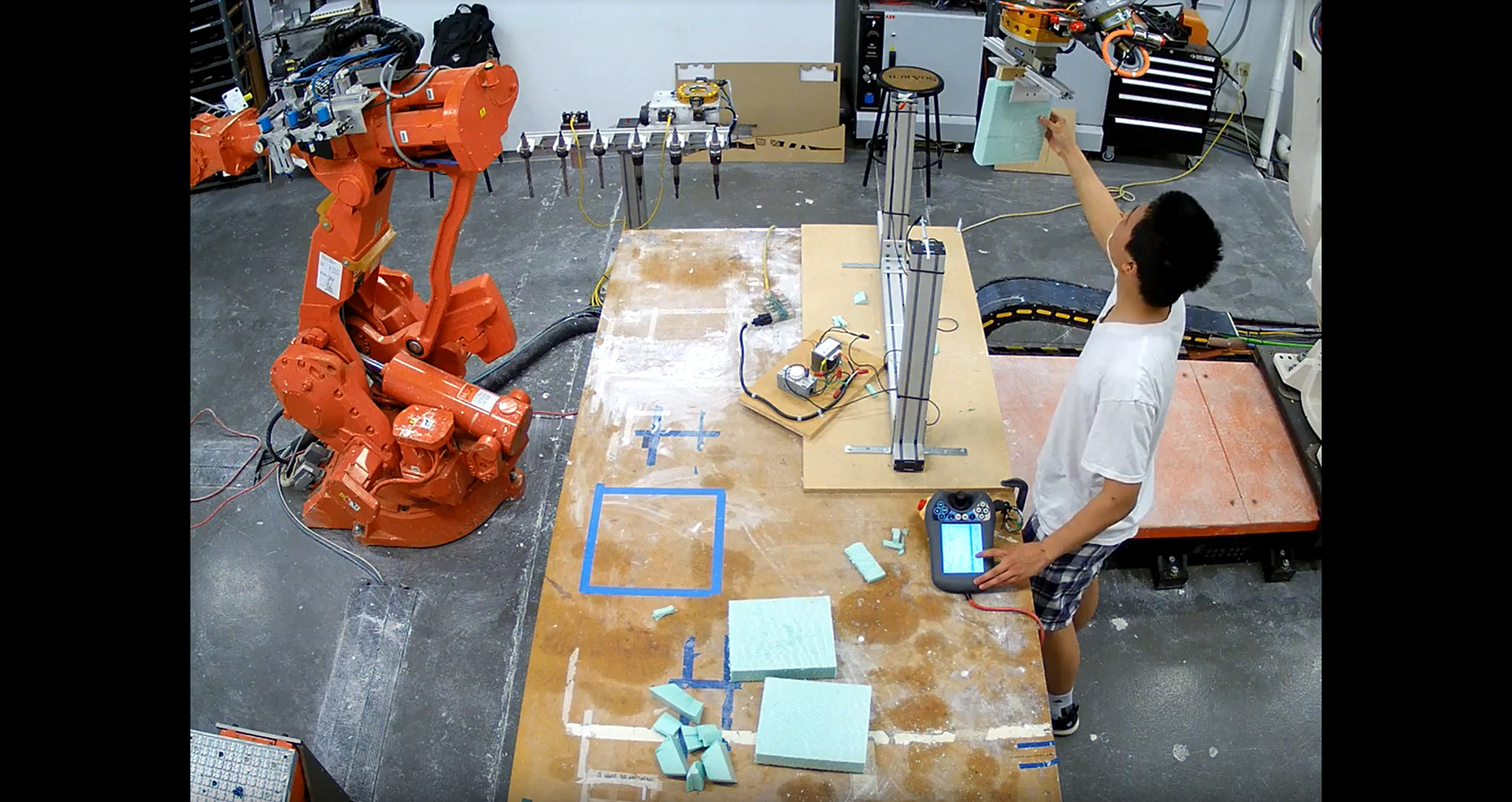
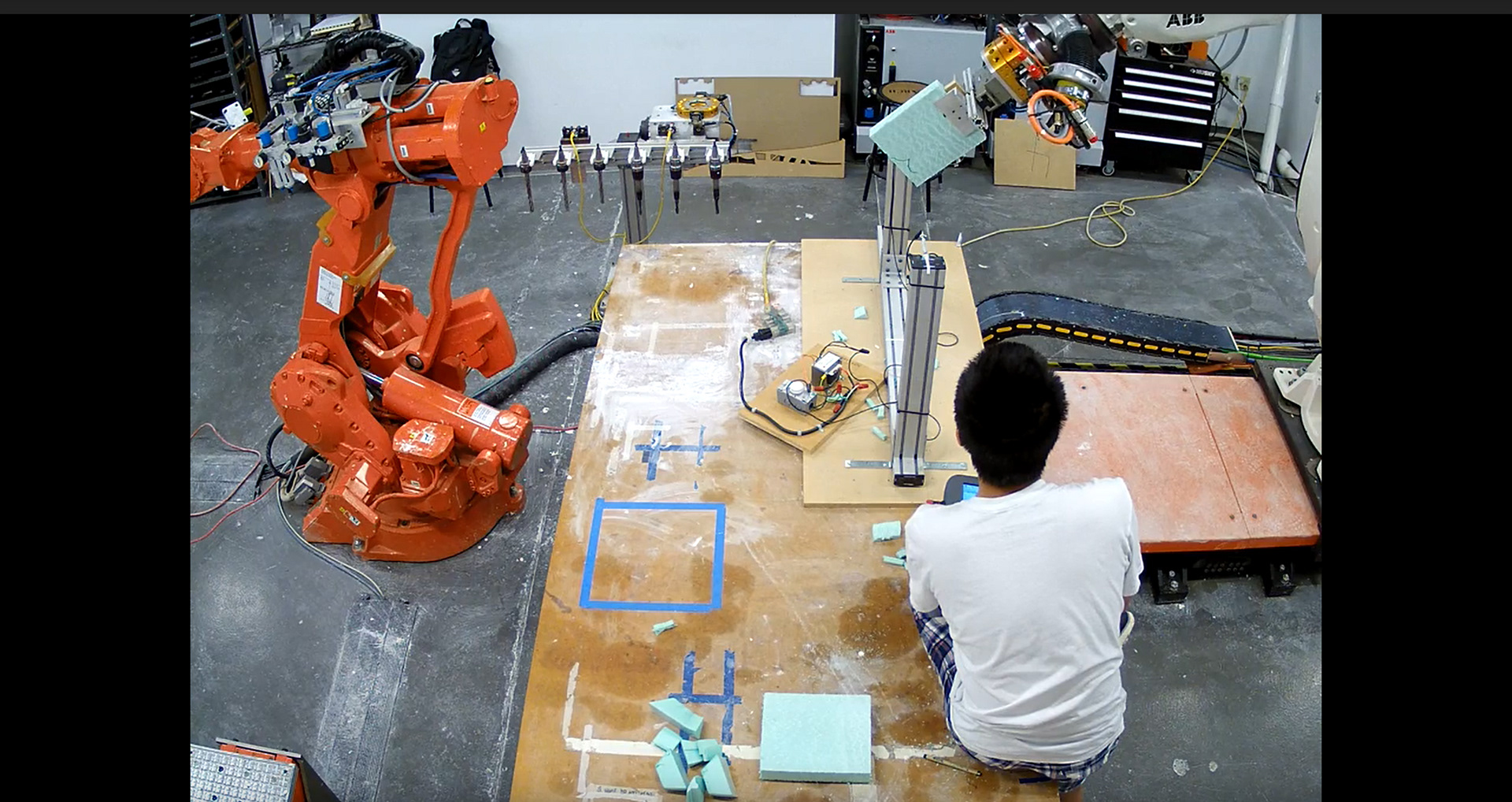
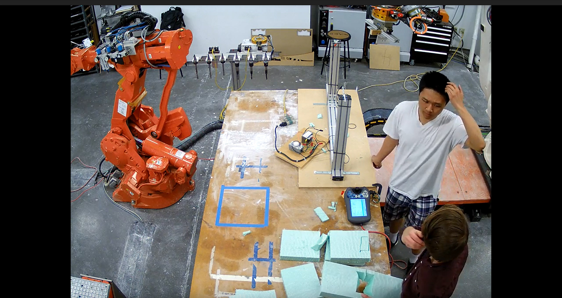
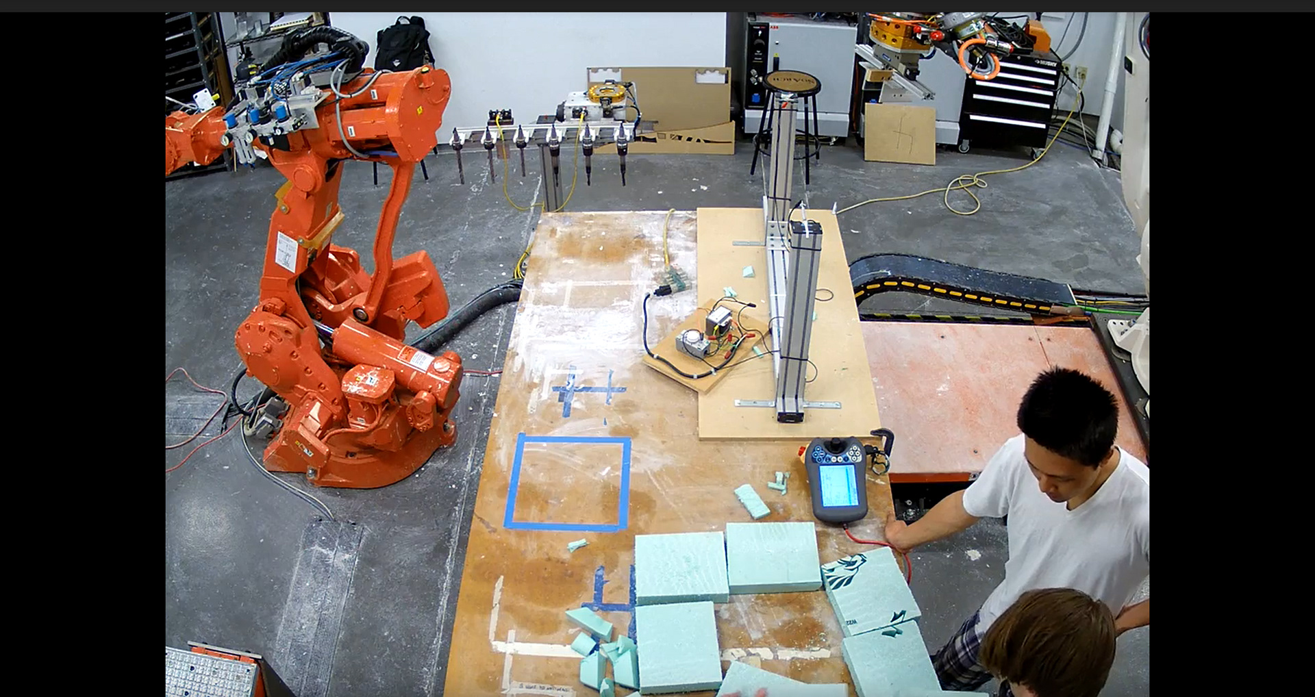
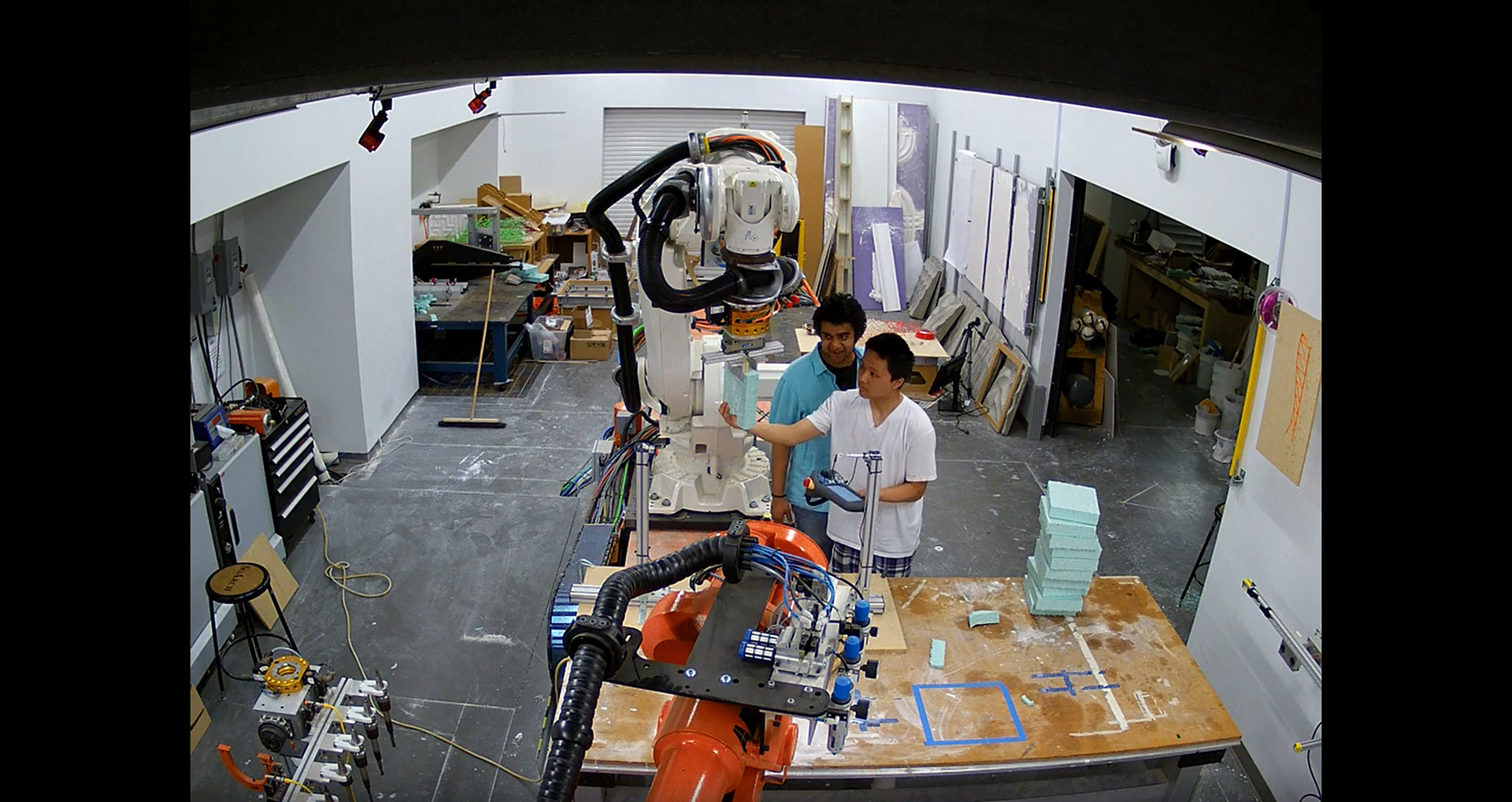
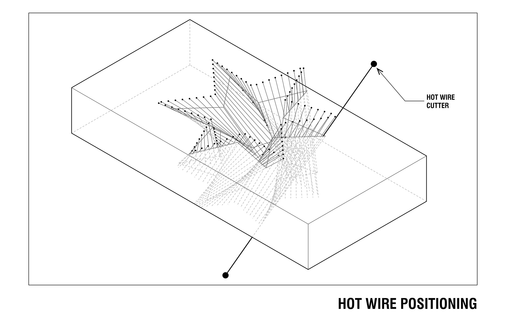
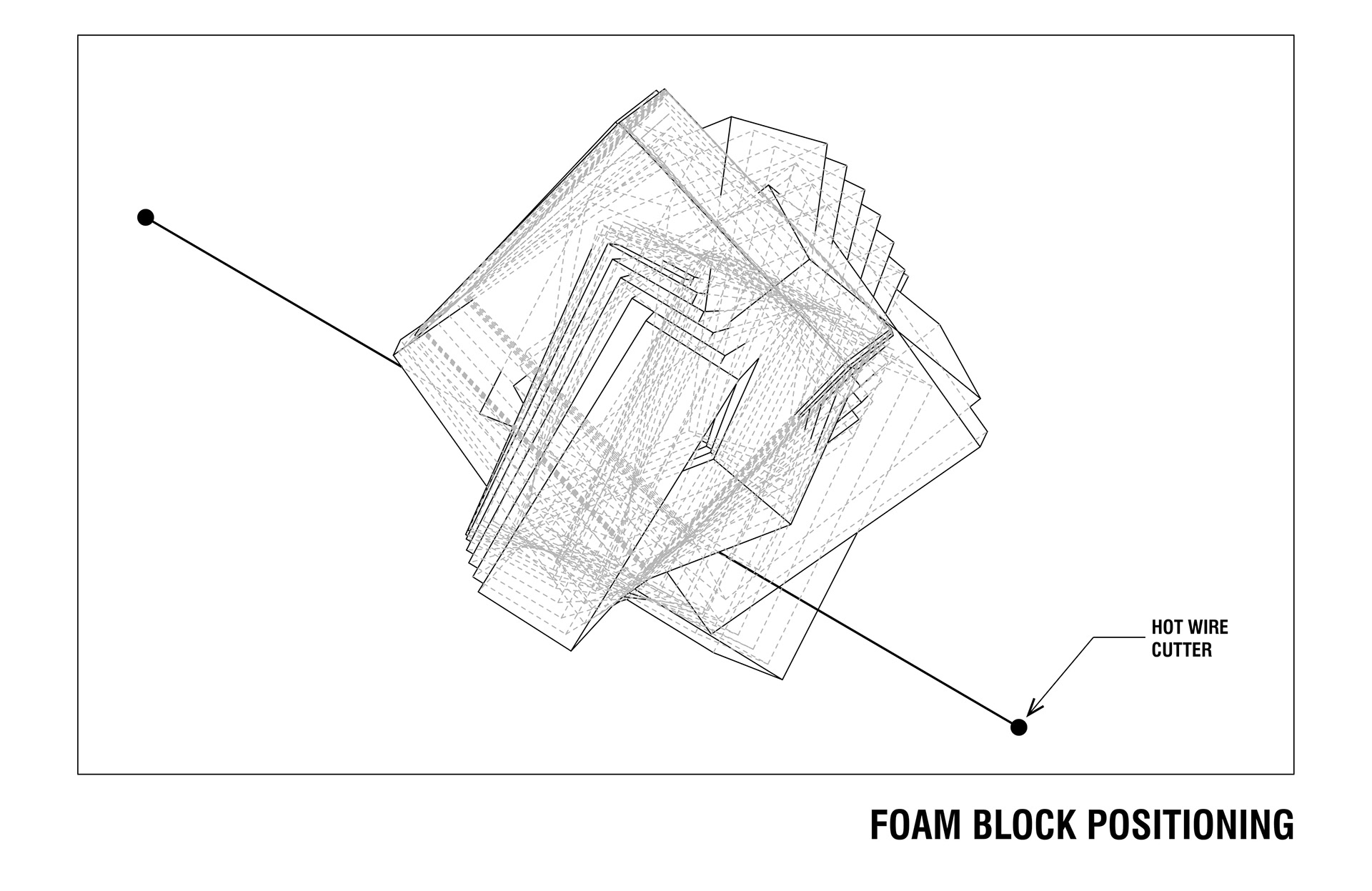
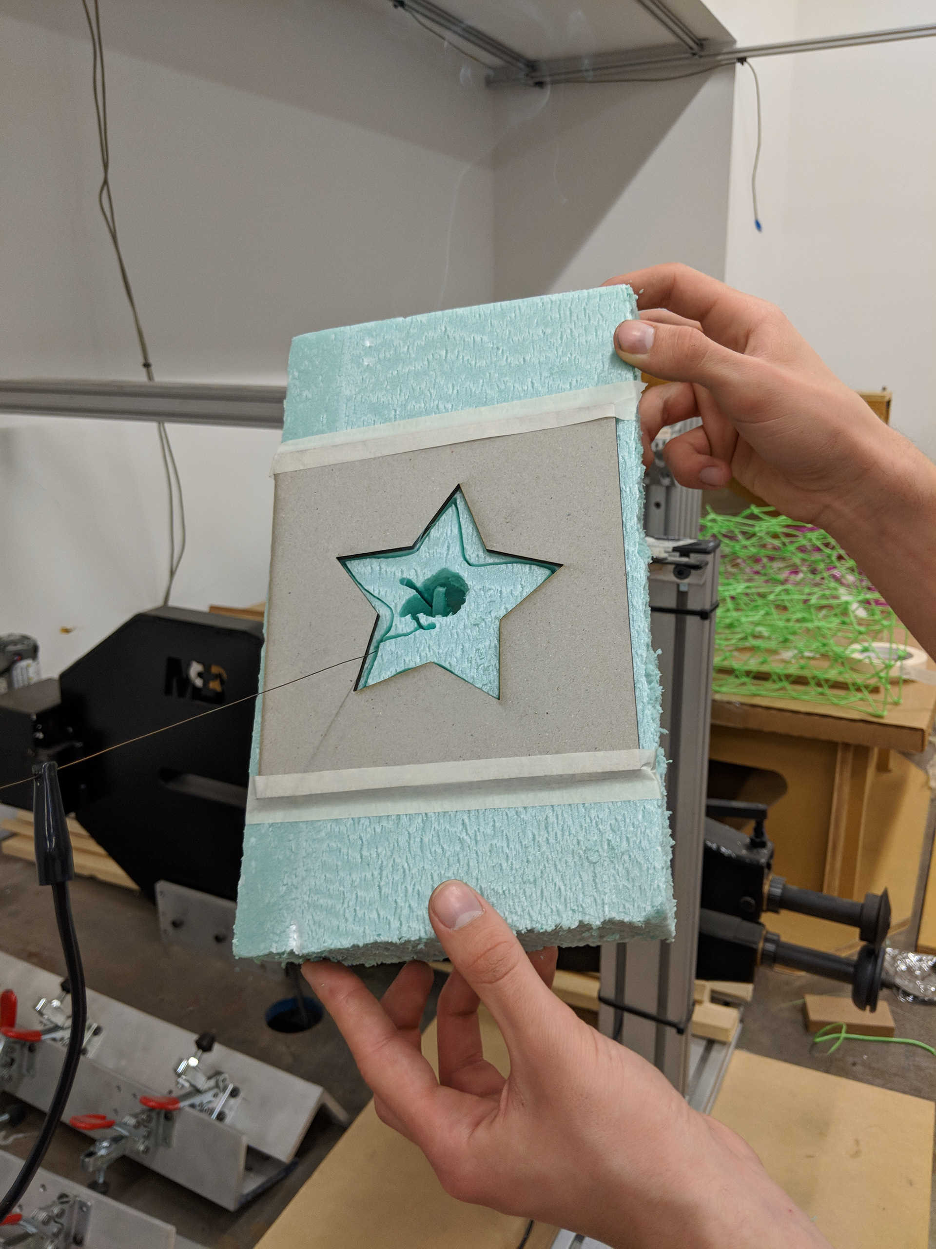
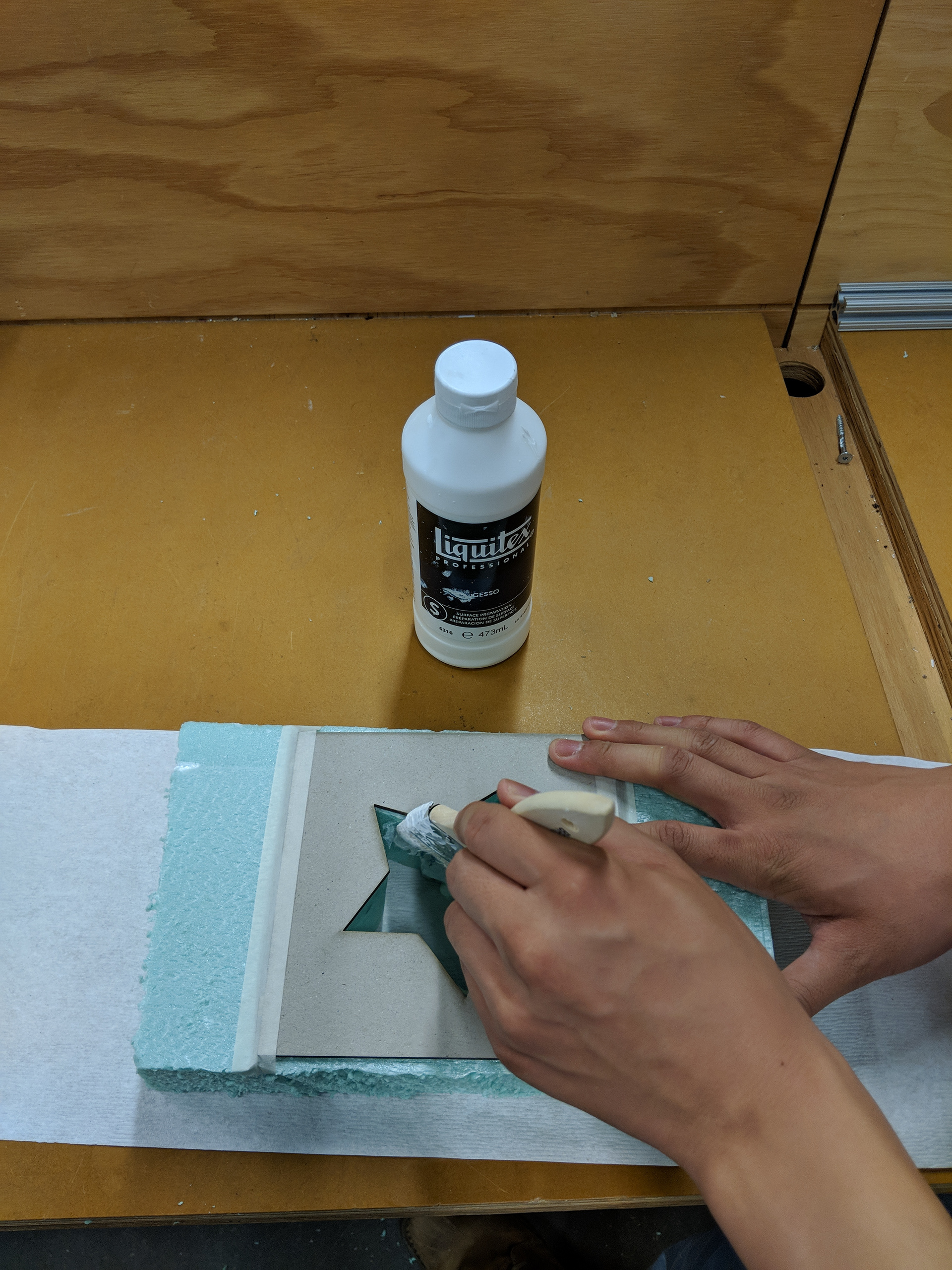
The procedure for this project was surprisingly less complicated than the setup. Generating the toolpaths proved challenging, but once we had them the fabrication went quite straightforward. Using HAL we generated a toolpath to map out the movement of the work object into the hot wire, tracing the outline of our geometry. This required a lot of continuous tweaking to ensure the robots positioning and orientation fell within its joint limits. We then exported the code, simulated it, and began our fabrication. The blocks had to be split into halves to allow the robot to cut the full thing, as well as make the mold easier to remove later on. Once we had the mold, a series of hand corrections was performed, trimming off unwanted portions and sanding edges. A gesso layer and rockite cast produced our final object.


Code Explanation
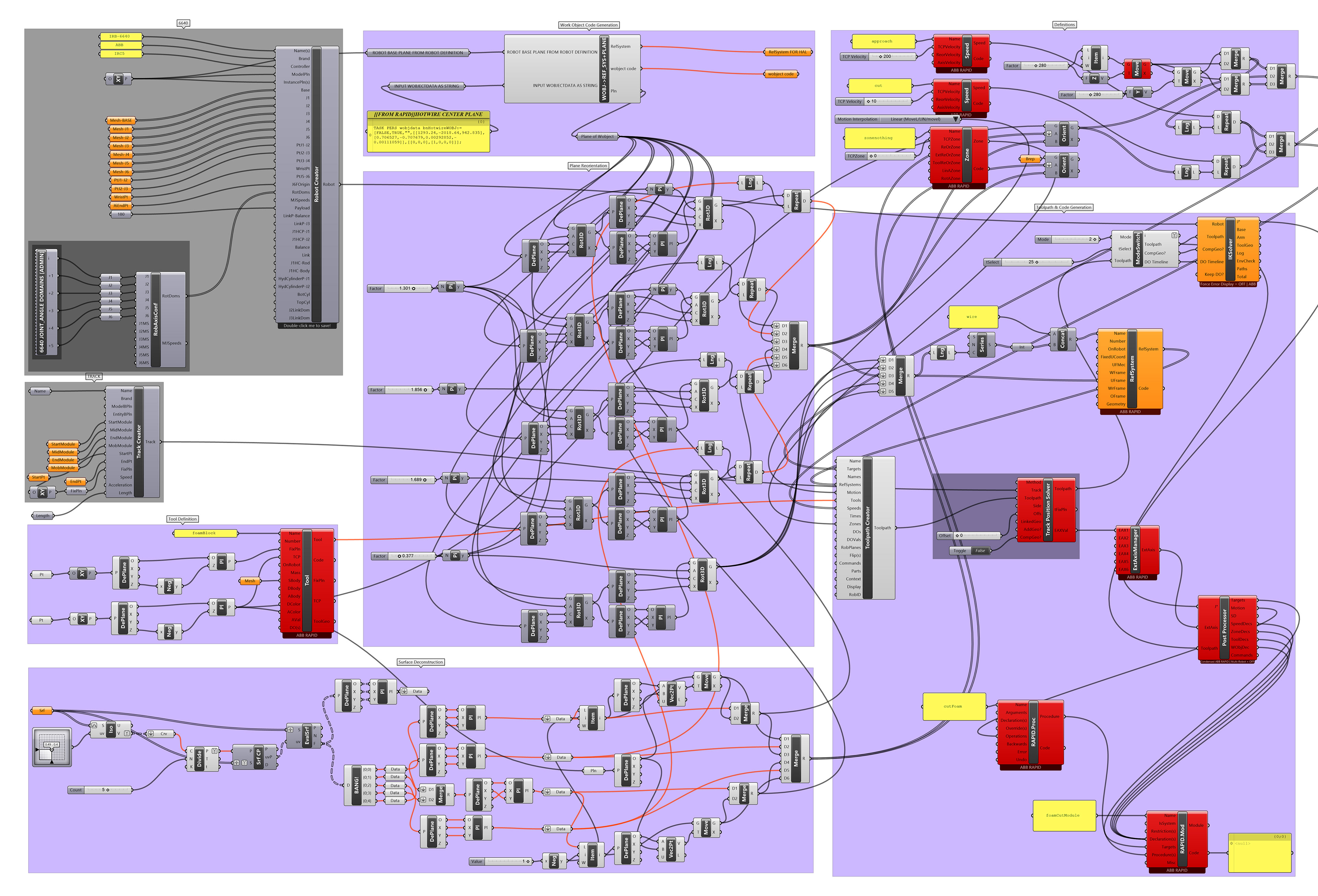
Transposing the form that was set as the goal required a series of transformations and complex reorienting of geometry to generate the RAPID code necessary to hotwire cut the foam molds. As previously mentioned, this project decided to simplify the cutting process by splitting each layer into two molds to decrease the range of orientations the robot would encounter and, in doing so, also reduce the chance of encountering coupling errors both in simulation and in execution of routines. The process of code generation began with the surfaces generated by splitting each layer in half to create 2 rotationally symmetrical pieces. These offered the surface geometries which were used as the driver surfaces that dictated the code for each piece. These surfaces were first divided into ruled surfaces, after which their surfaces frames were reoriented to that of the work object (the hot wire cutter). The work object was then rotated to get the robot in a comfortable position to be able to execute the code without encountering errors. This process was repeated until the code for all pieces was generated without issues then carried forward into RobotStudio to simulate.
Robot Fabrication Process